Diagnostic apparatus for an exhaust gas sensor

a technology of diagnostic equipment and exhaust gas, which is applied in the direction of electrical control, instruments, material electrochemical variables, etc., can solve the problems of deteriorating evaluation precision and the inability of the control unit to perform a correct control of the air-fuel ratio of the engine, and achieve the enhancement of detection precision the improvement of the detection accuracy of the deterioration failure of the exhaust gas sensor, and the effect of easy production

Active Publication Date: 2006-04-04
HONDA MOTOR CO LTD
View PDF11 Cites 32 Cited by
  • Summary
  • Abstract
  • Description
  • Claims
  • Application Information

AI Technical Summary

Benefits of technology

[0006]The present invention provides a deterioration failure diagnostic apparatus for an exhaust gas sensor that is disposed in an exhaust passage of an engine to generate an output corresponding to constituent elements of exhaust gas from the engine. The apparatus has detecting signal generating means for generating a detecting signal and multiplying the generated signal to a first basic fuel injection amount to produce a second fuel injection amount. The apparatus also includes a feedback representative value calculating means for calculating a feedback representative value based on feedback correction coefficients used at a normal operation time and multiplying it to the second fuel injection amount to produce a final fuel injection amount to be input to the engine. The apparatus further includes an exhaust gas sensor evaluating means for extracting from the output of the exhaust gas sensor a frequency response corresponding to the detecting signal. The output of the gas sensor is in response to the calculated final fuel injection amount. The condition of the exhaust gas sensor is determined based on the extracted frequency response. The feedback representative value is a value representing a steady-state deviation of the feedback correction coefficients. According to this invention, instead of using the composite signal corresponding to the modulated rectangular waveform and the exhaust gas level, the fuel amount multiplied by the detecting signal of a predetermined frequency is supplied, so that the ratio of the detecting frequency components contained in the exhaust gas can be kept at a higher level. Besides, in such situation, the condition of the exhaust gas sensor can be diagnosed based on the frequency response in the above-described frequency of the exhaust gas sensor output. Thus, the ratio of the noise elements contained in the exhaust gas can readily be decreased and the detection precision of the deterioration failure of the exhaust gas sensor may be improved. At the same time, by using the feedback representative value to correct the fuel injection amount during the deterioration failure detection process, increase of the exhaust gas elements during the detection process may be suppressed in comparison to the case of simply suspending the feedback.
[0007]According to one aspect of the present invention, the feedback representative value is a value representing a steady-state deviation of the feedback correction coefficients used before the start of a process for detecting the degradation failure of the exhaust gas sensor. Specifically, the feedback representative value is an average, a median or a smoothed value of the feedback correction coefficients. According to this aspect of the invention, since the feedback representative value is calculated based on the average or the like of the feedback correction coefficients used before the start of the degradation failure detection process, the fuel injection amount can be corrected by the feedback representative value that is adapted to the characteristic of the engine and accordingly the increase of the exhaust gas elements during the detection process can be suppressed.
[0008]According to another aspect of the invention, the detecting signal to be multiplied to the first basic fuel injection amount is a signal obtained by adding either a sine wave or a cosine wave or a trigonometric wave to a predetermined offset value. According to this aspect of the invention, signals that are easy to produce are used. While the ratio of the frequency components for the detection is maintained substantial and the magnitude of the detecting frequency components in the exhaust gas is maintained substantial, the response of specific frequencies of the exhaust gas sensor is used for the evaluation purpose so that the detection precision of the deterioration failure of the exhaust gas sensor may be further improved.

Problems solved by technology

Therefore, when the exhaust gas sensor does not produce outputs reflecting a correct air-fuel ratio due to its degradation failure, the control unit cannot perform a correct control of the air-fuel ratio upon the engine.
Therefore, when the sensor condition is evaluated based on such output, evaluation precision may deteriorate.

Method used


Image

  • Diagnostic apparatus for an exhaust gas sensor
  • Diagnostic apparatus for an exhaust gas sensor
  • Diagnostic apparatus for an exhaust gas sensor

Examples


Embodiment Construction

1. Description of Functional Blocks

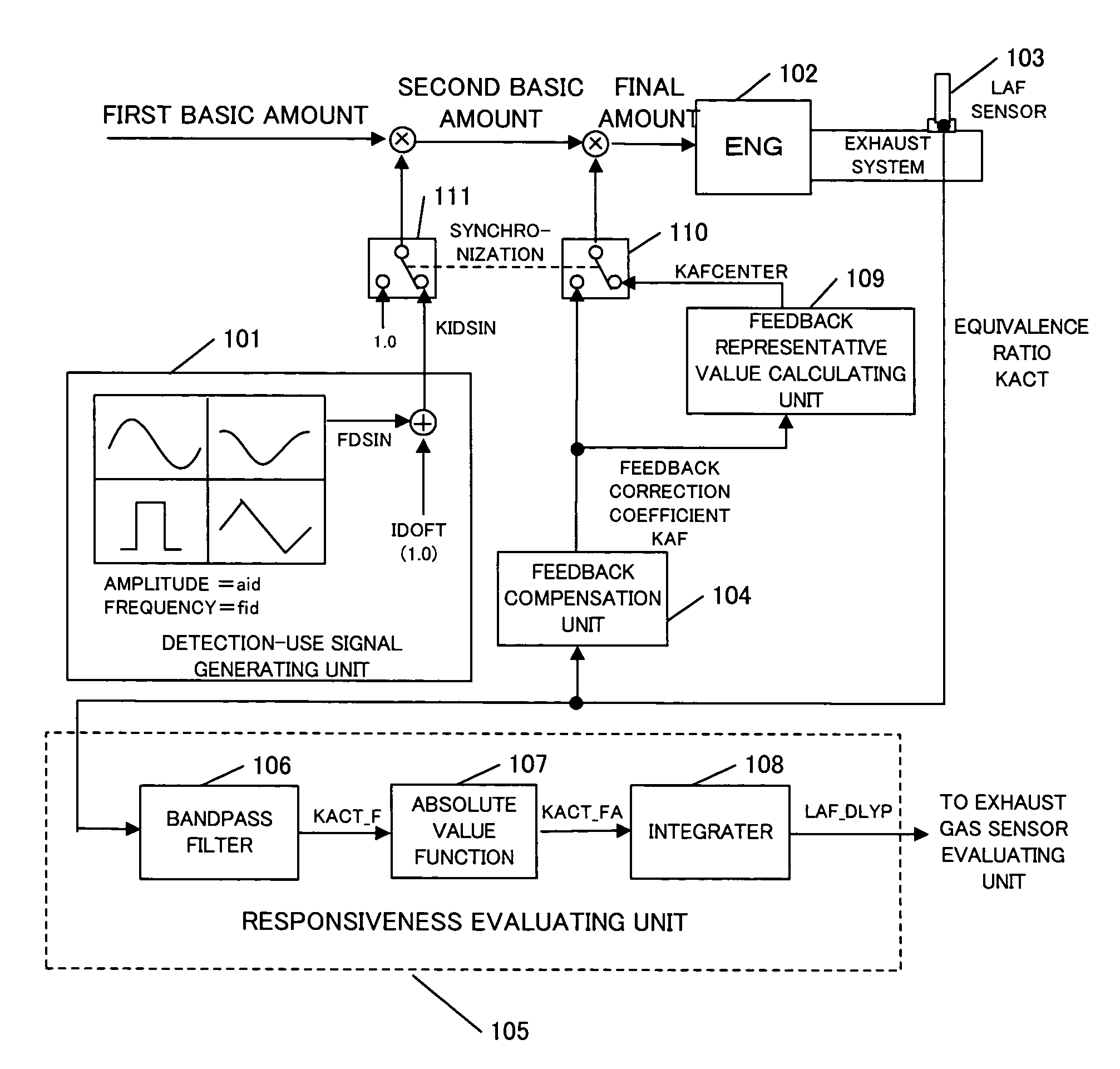
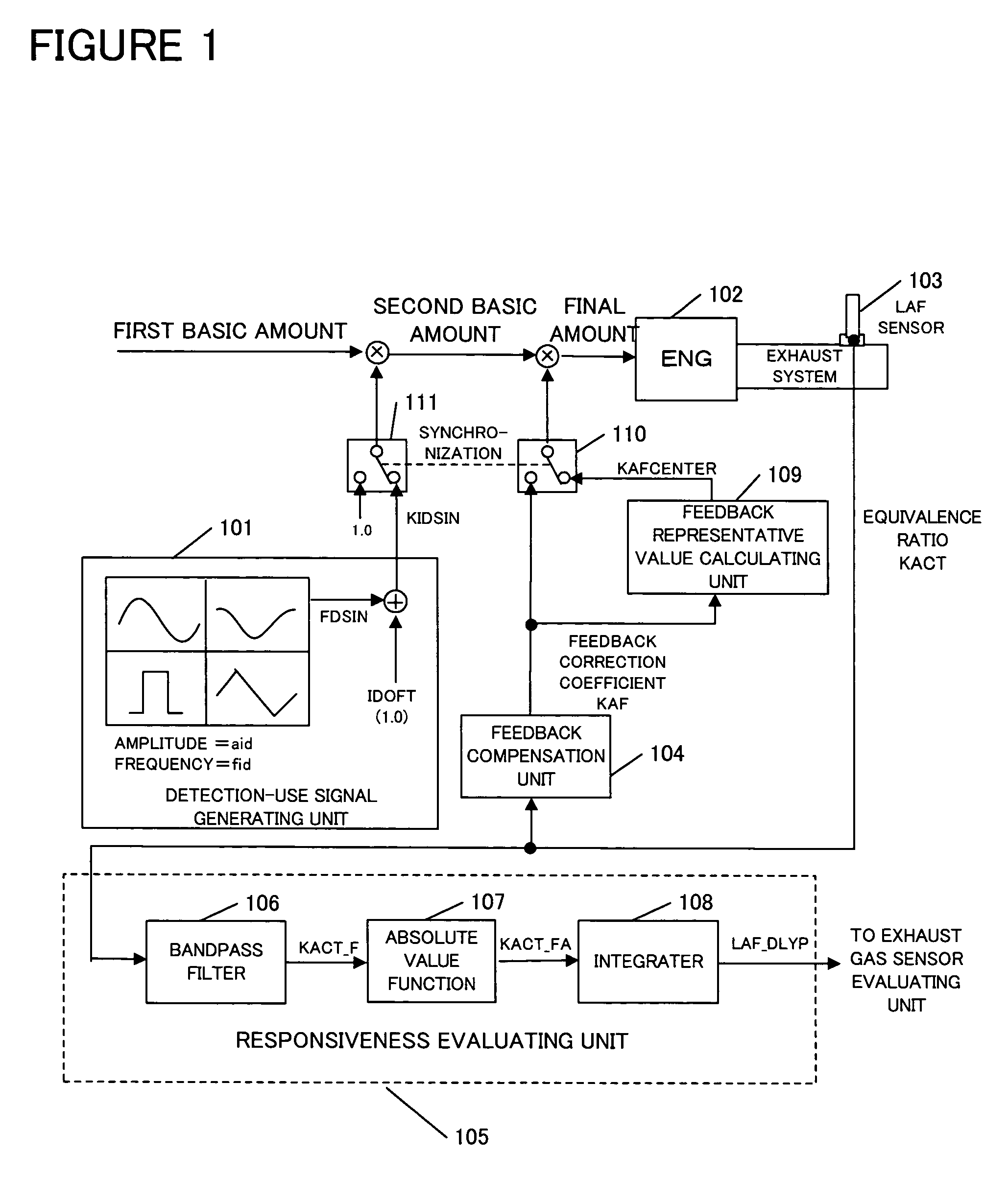
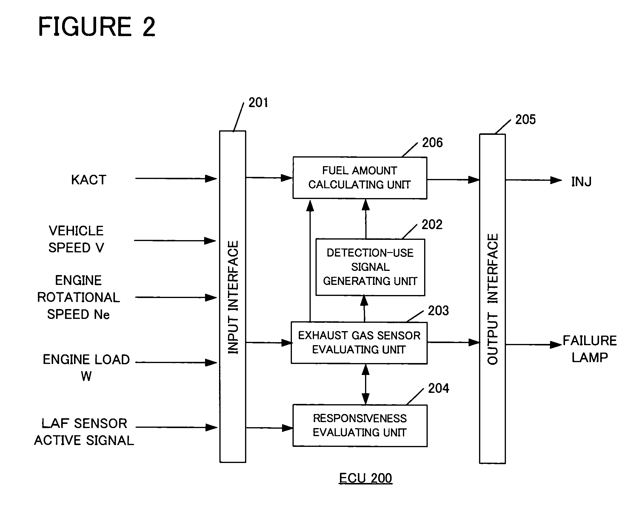
[0024]Each functional block will be described with reference to FIG. 1 and FIG. 2. FIG. 1 is a schematic diagram of an overall structure for describing a concept of the present invention.

[0025]A detecting-signal generating unit 10 has a function of generating a predetermined detecting signal KIDSIN in which a trigonometric function wave FDSIN or the like is superimposed on an offset value IDOFT. A responsiveness evaluating unit 105 has a function of performing a bandpass filtering upon an equivalence ratio KACT, which is an output from a wide-range linear air-fuel ratio sensor (hereinafter referred to as an LAF sensor) 103, then converting the filtered value to an absolute value, further integrating the converted values over a predetermined time period and finally transmitting this integral value to an exhaust gas sensor evaluating unit. The exhaust gas sensor evaluating unit has a function of determining a degradation failure of an exhaust gas sen...


PUM


Abstract

A deterioration failure diagnostic apparatus is provided for diagnosing an exhaust gas sensor disposed in an exhaust passage of an engine. The apparatus has a unit for generating a detecting signal and multiplying the generated signal to a first basic fuel injection amount to produce a second fuel injection amount. The apparatus includes a unit for calculating a feedback representative value based on feedback correction coefficients and multiplying the feedback representative value to the second fuel injection amount to produce a final fuel injection amount to be input to the engine. The apparatus includes a unit for extracting a frequency response corresponding to the detecting signal from an output of the exhaust gas sensor of the engine, the output being responsive to the calculated final fuel injection amount. A condition of the exhaust gas sensor is determined based on the extracted frequency response.

Description

BACKGROUND OF THE INVENTION[0001]The present invention relates to a diagnostic apparatus for detecting a degradation failure of an exhaust gas sensor disposed in an exhaust passage of an internal-combustion engine (hereinafter referred to as an “engine”).[0002]An exhaust gas sensor is generally disposed in an exhaust passage of an engine of a vehicle in order to measure constituent elements of an exhaust gas. The exhaust gas sensor produces outputs representing air-fuel ratio of the exhaust gas. Based on the output value, an electronic control unit of the engine controls the air-fuel ratio of the fuel to be supplied to the engine. Therefore, when the exhaust gas sensor does not produce outputs reflecting a correct air-fuel ratio due to its degradation failure, the control unit cannot perform a correct control of the air-fuel ratio upon the engine.[0003]There are disclosed some techniques for detecting a degradation failure of such exhaust gas sensor. The Japanese Patent Application ...

Claims


Application Information

Patent Timeline
Patent Type & Authority Patents(United States)
IPC IPC(8): F02D41/22F02D41/14G01M15/00F01N3/00F02D45/00F01N3/20
CPCF02D41/1454F02D41/1495F02D41/1456
Inventor MAKI, HIDETAKAKITAGAWA, HIROSHITSUDA, MASAKI
Owner HONDA MOTOR CO LTD
Why Eureka
Try Eureka