Front end structure of vehicle with labyrinth structure forming means for cooling air to a radiator

Inactive Publication Date: 2006-04-04
DENSO CORP
View PDF15 Cites 9 Cited by
  • Summary
  • Abstract
  • Description
  • Claims
  • Application Information

AI Technical Summary

Benefits of technology

[0007]The above-mentioned problem being taken into account, the objective of the present invention is to provide a novel structur

Problems solved by technology

In a general front end structure, a shroud is provided in order to prevent a current of air caused by an air blower from flowing around a radiator but, as the shroud forms a kind of an air duct connecting the radiator and the air blower, it is impossible to direct the current of air, which is created by movement of a vehicle and flows through a clearance between the radiator and the vehicle body, to the radiato

Method used


Image

  • Front end structure of vehicle with labyrinth structure forming means for cooling air to a radiator
  • Front end structure of vehicle with labyrinth structure forming means for cooling air to a radiator
  • Front end structure of vehicle with labyrinth structure forming means for cooling air to a radiator

Examples


first embodiment

[0024](First Embodiment)

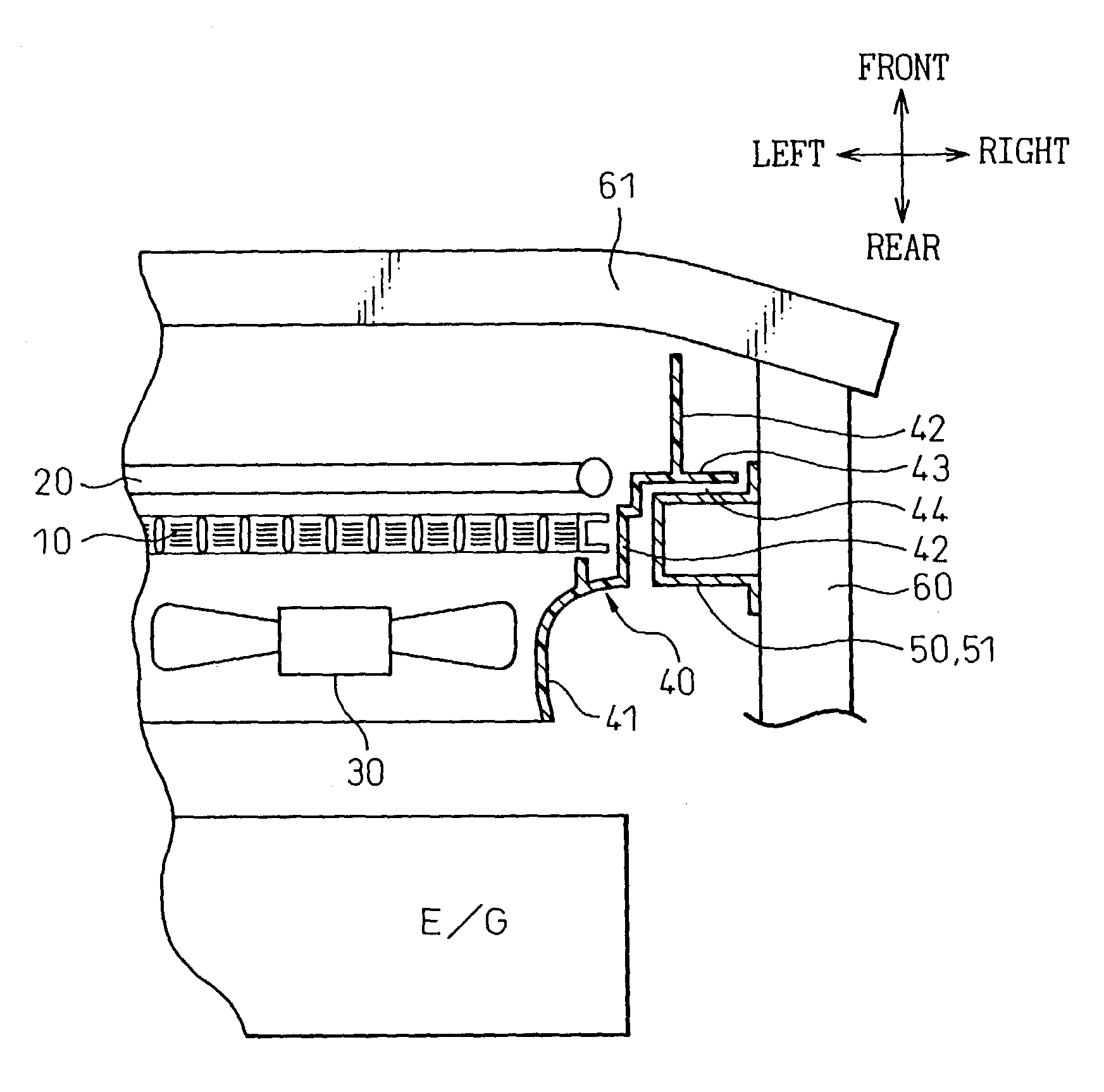
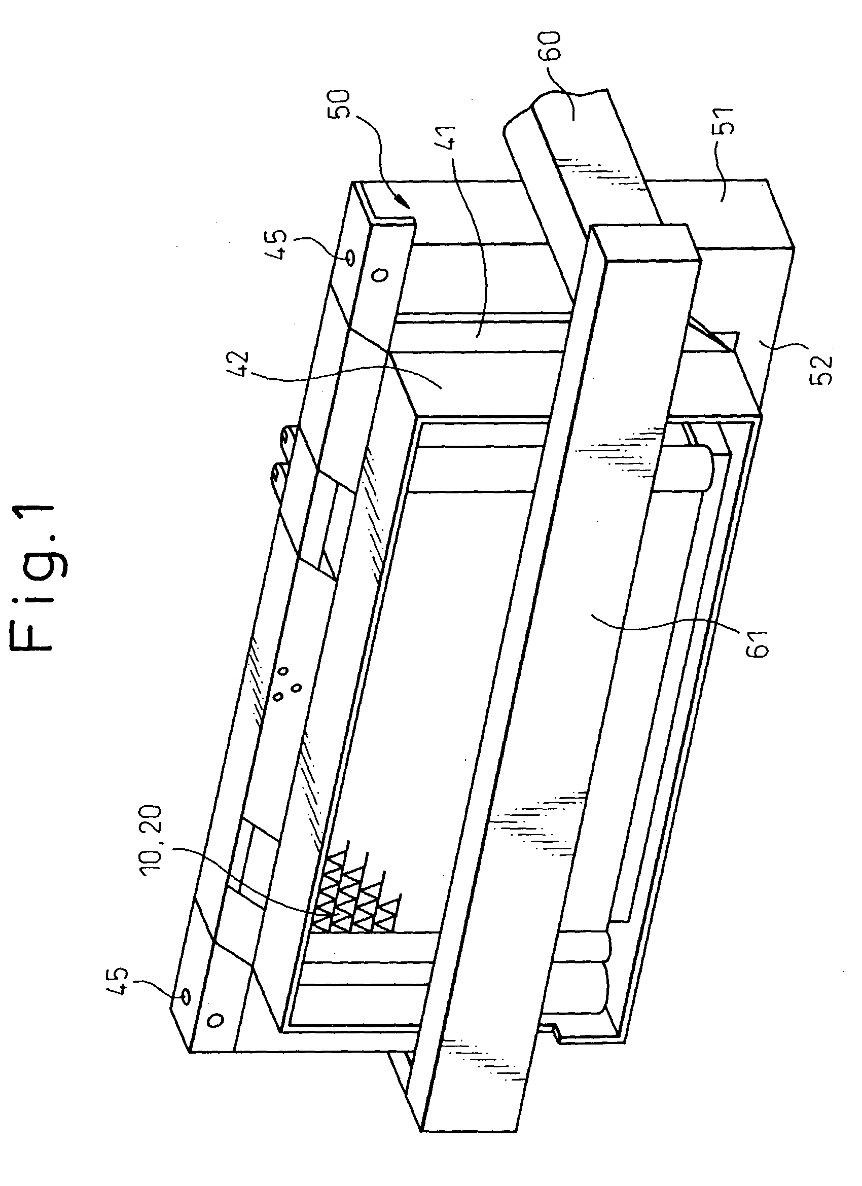
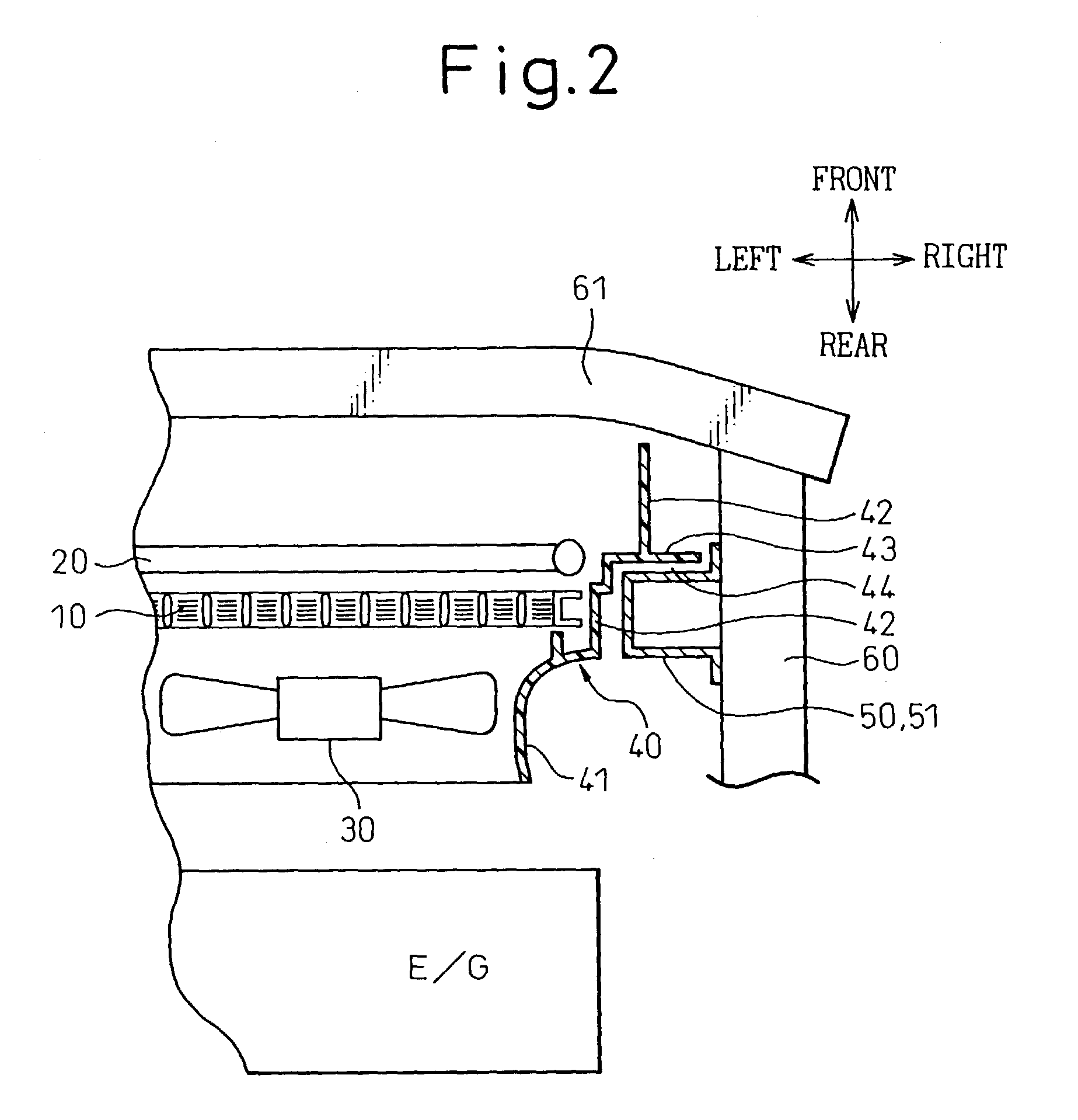
[0025]FIG. 1 is a perspective view of the front end structure of a vehicle in the prevent embodiment, FIG. 2 is a sectional view, when viewed from the top, of a structure where a radiator 10 and a duct shroud 40 are fixed, and FIG. 3 is a perspective view of the duct shroud 40.

[0026]In FIG. 1, the radiator 10 is a heat exchanger that exchanges heat between engine cooling water and air and there is mounted a condenser 20, which is an outside heat exchanger of an air conditioner, on the upstream side of the radiator 10, as shown in FIG. 2. The condenser 20 is fixed to a header tank of the radiator 10 so that it can be removed and attached by a mechanical fastening means such as bolts.

[0027]An air blower 30 is an axial-flow fan type, which is arranged on the downstream side of the radiator 10 and supplies cooling air to the radiator 10 and the condenser 20, a shroud 41 is a kind of cover, which prevents a current of air created by the air blower 30 from flowing ...

second embodiment

[0039](Second Embodiment)

[0040]Although the flange 43 is integrally formed into the duct 42 in the first embodiment, in the present embodiment, after the flange 43 and a part of the duct 42 are separately manufactured, the flange 43 is integrally formed into the duct shroud 40 by means of mechanical fastening structures such as one in which screws or claws are inserted, or by welding.

third embodiment

[0041](Third Embodiment)

[0042]In the embodiment described above, the labyrinth-structured clearance 44 is formed by arranging the flange 43 in front of the pillar 51 but, in the present embodiment, the labyrinth-structured clearance 44 is formed by arranging the flange 43 behind the pillar 51, as shown in FIG. 5.

[0043]In the present embodiment however, as a part 42b of the duct 42 near the shroud 41 and a part 42a of the duct 42 near the point (front end) are formed into one body by a mechanical tightening means, welding, or the like after they are manufactured separately, it is possible to repair or replace with ease only the part 42a near the point that is easily damaged in a collision. Therefore, it is possible to suppress a rise in the repair cost while enhancing replacement efficiencies after a collision.


PUM


Abstract

A clearance 44 is provided between the outer periphery of a duct 42 and a vehicle body, that is, a radiator support 50 and, at the same time, the clearance 44 is made to have a labyrinth structure. In this structure, it is possible to prevent vibrations of the vehicle body from being propagated from the radiator support 50 to the duct 42 while preventing a current of air, such as one caused by movement of the vehicle, from flowing around heat exchangers, such as a radiator 10, and flowing downstream through the clearance 44. Therefore, it is possible to improve the cooling performance of heat exchangers such as the radiator 10 while preventing the duct 42, that is, a duct shroud 40 from being damaged by vibration.

Description

BACKGROUND OF THE INVENTION[0001]1. Field of the Invention[0002]The present invention relates to a front end structure of a vehicle.[0003]2. Description of the Related Art[0004]In a general front end structure, a shroud is provided in order to prevent a current of air caused by an air blower from flowing around a radiator but, as the shroud forms a kind of an air duct connecting the radiator and the air blower, it is impossible to direct the current of air, which is created by movement of a vehicle and flows through a clearance between the radiator and the vehicle body, to the radiator, though the current of air caused by the air blower passes through the radiator without fail.[0005]Contrary to this, in the invention disclosed in Japanese Patent No. 3191385, air is prevented from flowing through a clearance between a heat exchanger (a radiator etc.) and the vehicle body by providing a rectangular pipe-shaped duct that covers the outer peripheral part of the heat exchanger and, at th...

Claims


Application Information

Patent Timeline
IPC IPC(8): B60K11/04B62D25/08
CPCB62D25/084B60K11/04
Inventor MAEDA, NORIAKIOZAWA, IKUOSUGIYAMA, TOSHIKI
Owner DENSO CORP
Why Eureka
Try Eureka