Image reader using off-axial optical system for imaging optical system

a technology of optical system and image reader, applied in the direction of electromagnetic radiation sensing, printers, instruments, etc., can solve the problems of reducing resolution, difficult to adopt carriage-integrated scanning system, lightening of imaging lens,

Inactive Publication Date: 2006-04-04
CANON KK
View PDF27 Cites 2 Cited by
  • Summary
  • Abstract
  • Description
  • Claims
  • Application Information

AI Technical Summary

Problems solved by technology

Further, making the imaging lens lighter, however, decreases resolution because of an increased angle of view.
As such, it was therefore difficult to adopt the carriage-integrated scanning system.
The above-mentioned references, however, do not disclose fixing means and adjusting means for the reflecting mirrors, the imaging mirrors having the off-axial reflecting surfaces, and the line sensors in the off-axial optical system adopted to the image readers of the carriage-integrated scanning system.
Accordingly, in working the reflecting surfaces, when one reflecting surface is corrected, the free-form surfa...

Method used


Image

  • Image reader using off-axial optical system for imaging optical system
  • Image reader using off-axial optical system for imaging optical system
  • Image reader using off-axial optical system for imaging optical system

Examples


Embodiment Construction

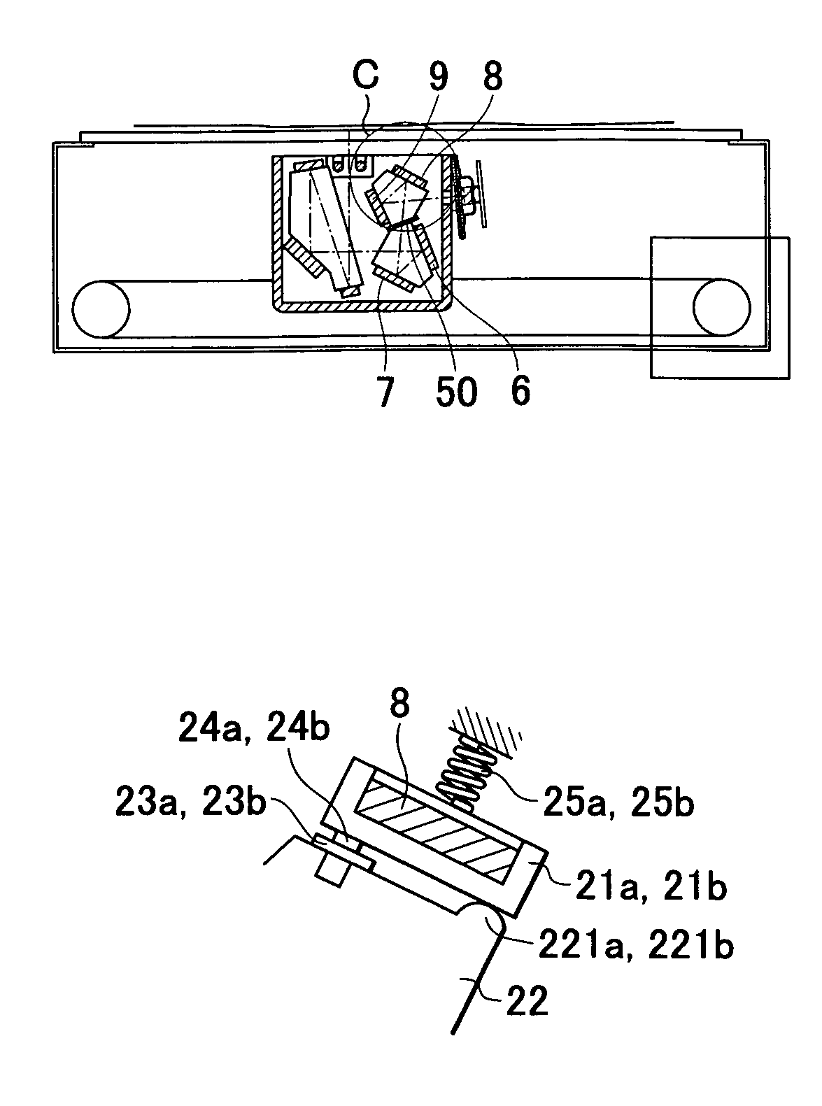
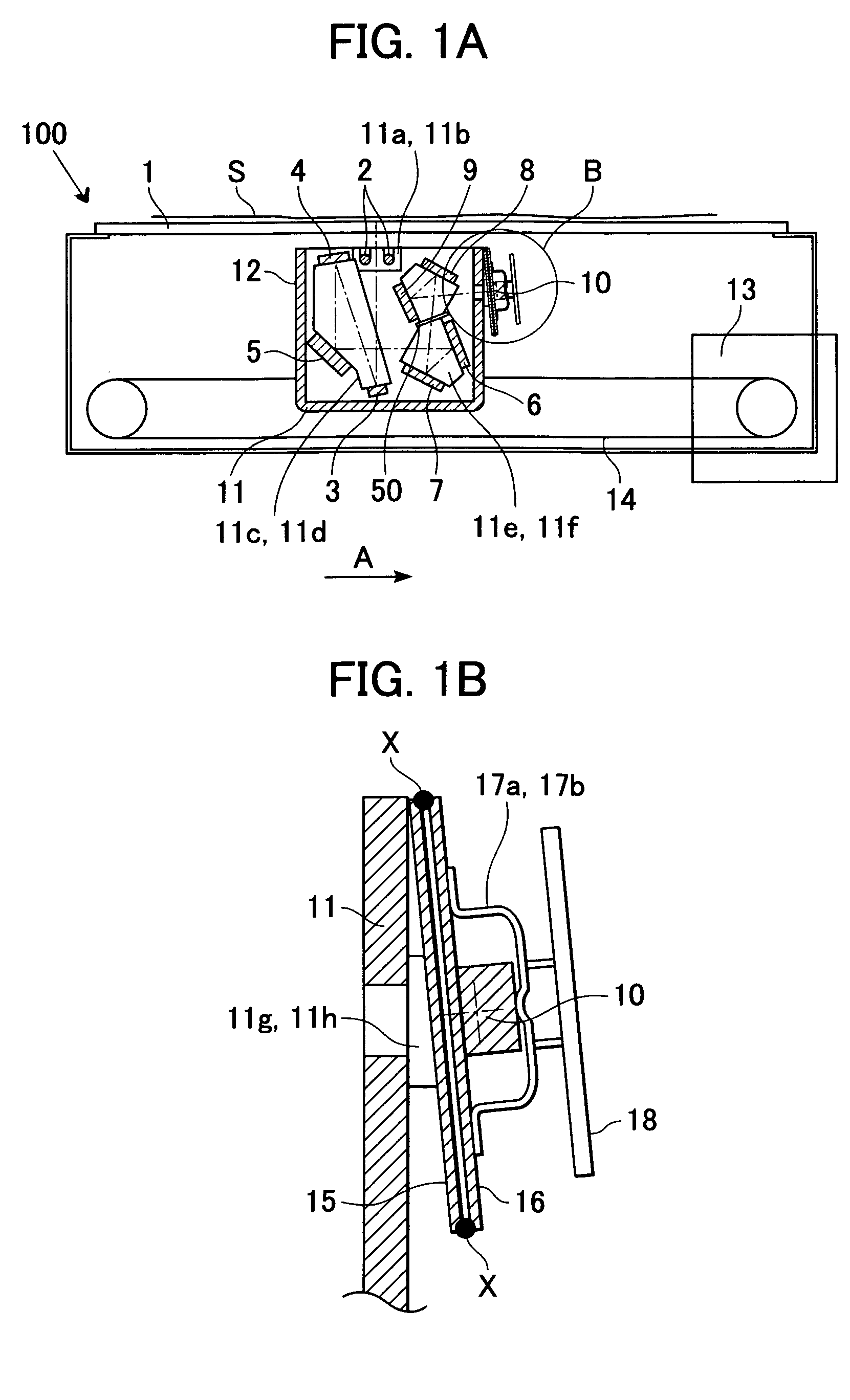
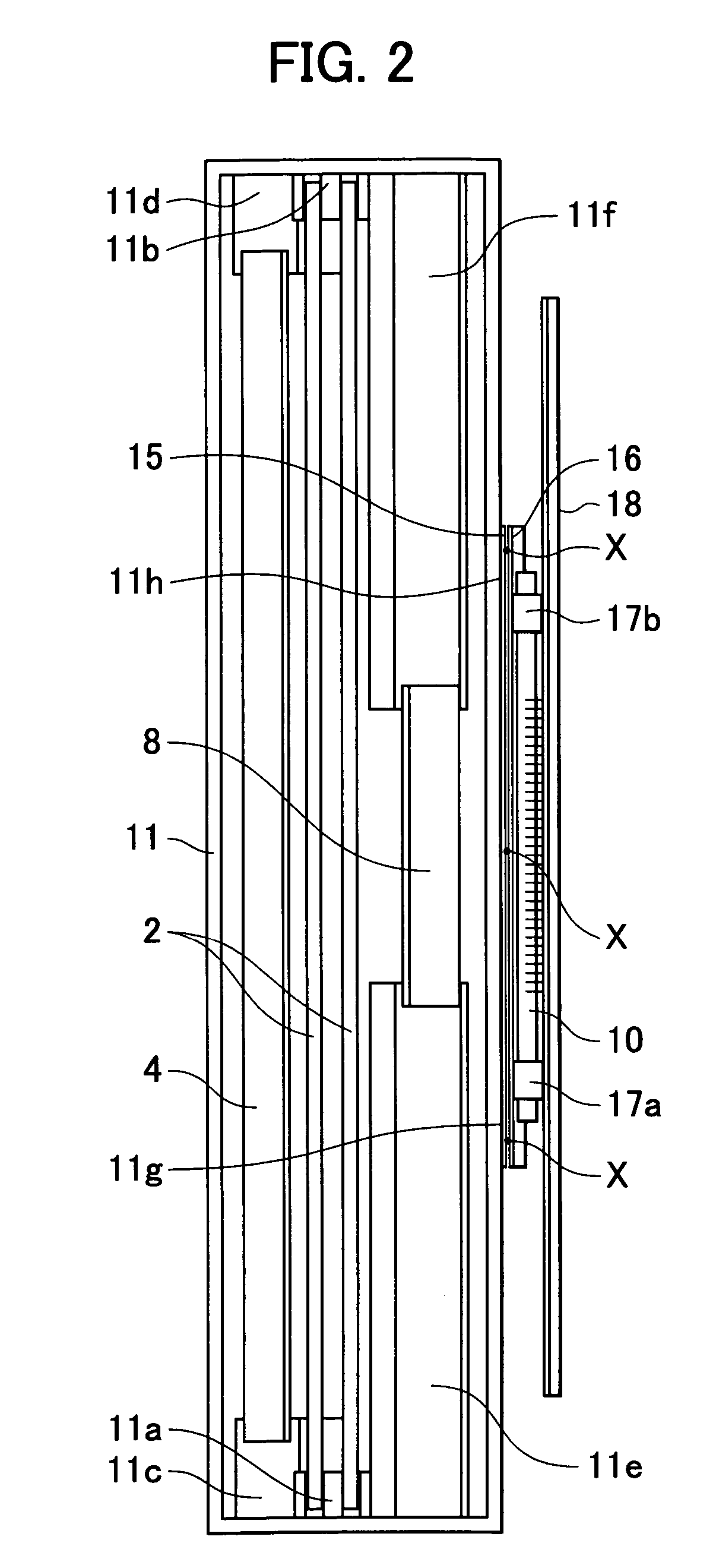
[0025]FIG. 1A is a sectional view of an image reader 100 according to one embodiment of the present invention. The image reader 100 can be incorporated in an image scanner or a copying machine. FIG. 1B is an enlarged view of a portion of the image reader 100 defined by circle B shown in FIG. 1A. FIG. 1B shows details of a CCD (line sensor) 10. FIG. 2 is a top view of a carriage 12 of the image reader 100 shown in FIG. 1.

[0026]A document S is placed on a document glass plate 1. A light source 2 serving as an illuminator can be, for example, a xenon lamp. First, second, and third reflecting mirrors 3, 4, and 5 refract the optical path of light flux coming from the document S. Each of first, second, third and fourth imaging mirrors 6–9 has an off-axial reflecting surface, which refracts the light flux using air as medium to form an image on the line sensor 10. The imaging mirrors 6–9 can be formed from resin such as polycarbonate. A diaphragm 50 is provided in the optical path between ...


PUM


Abstract

An image reader adopting an off-axial optical system, an adjustable imaging mirror and a CCD fixed to a highly rigid structure. Since the relative position between reflecting and imaging mirrors can be set highly accurately, adjusting only the CCD-mounting position allows a required specification of the read image to be met. The imaging mirror can easily be adjusted without distorting the reflecting surface. The reflecting and imaging mirrors, and the CCD-mounting-position adjuster are positioned directly to reflecting-mirror supporting sections, imaging-mirror supporting sections, and CCD supporting sections, which are integrated with a carriage casing, and fixed to them. The CCD is fixed to the carriage casing with the CCD-mounting-position adjuster. An imaging mirror close to a diaphragm and adjacent to the image is supported by a mirror adjusting plate, which can be displaced to adjust the position of the imaging mirror.

Description

BACKGROUND OF THE INVENTION[0001]1. Field of the Invention[0002]The present invention relates to an imaging means for reading a document and an image reader using the same.[0003]2. Description of the Related Art[0004]Image scanners serving as image readers for reading image information on document surfaces have been disclosed in, for example, Japanese Patent Laid-Open No. 3-113961.[0005]Such image scanners read image information by exposure-scanning the document surface, which involves moving only a reflecting mirror while an imaging lens and a line sensor are fixed.[0006]In order to simplify the device structure, a carriage-integrated scanning system has been employed which scans a document surface with an imaging lens, line sensor and so on, which are integrated together.[0007]FIG. 3 shows an image reader of a conventional carriage-integrated scanning system. Light flux, emitted from a light source 501, illuminates a document 503 placed on a document glass plate 502. The light flu...

Claims


Application Information

Patent Timeline
IPC IPC(8): G06K7/10G02B7/182G02B7/198G03B27/50H04N1/028H04N1/10H04N1/19
CPCG02B7/1824H04N1/0303H04N1/1017H04N2201/0242H04N2201/02433H04N2201/02441H04N2201/04796H04N2201/02447
Inventor AOYAMA, TAKESHIIWATA, HYOEMIURA, YUKIHIROKISHI, TAKEHIROSUGA, TAKAYUKI
Owner CANON KK
Why Eureka
Try Eureka