Printhead cap assembly for an ink jet printer

a technology of ink jet printers and capping assemblies, applied in printing and other directions, can solve the problem of not providing adequate water containment evaporation

Active Publication Date: 2006-04-04
FUNAI ELECTRIC CO LTD +2
View PDF28 Cites 11 Cited by
  • Summary
  • Abstract
  • Description
  • Claims
  • Application Information

AI Technical Summary

Benefits of technology

[0012]An advantage of the invention is the ability to establish water containment evaporation with respect to a capped printhead at a desired evaporation loss rate by selection of an appropriate vent path length to width and / or depth ratio.
[0013]Another advantage of the invention is the ability to establish an appropriate vent path length in a relatively small area.

Problems solved by technology

However, where such an effective seal is formed, such a system may not provide adequate water containment evaporation.

Method used


Image

  • Printhead cap assembly for an ink jet printer
  • Printhead cap assembly for an ink jet printer
  • Printhead cap assembly for an ink jet printer

Examples


Embodiment Construction

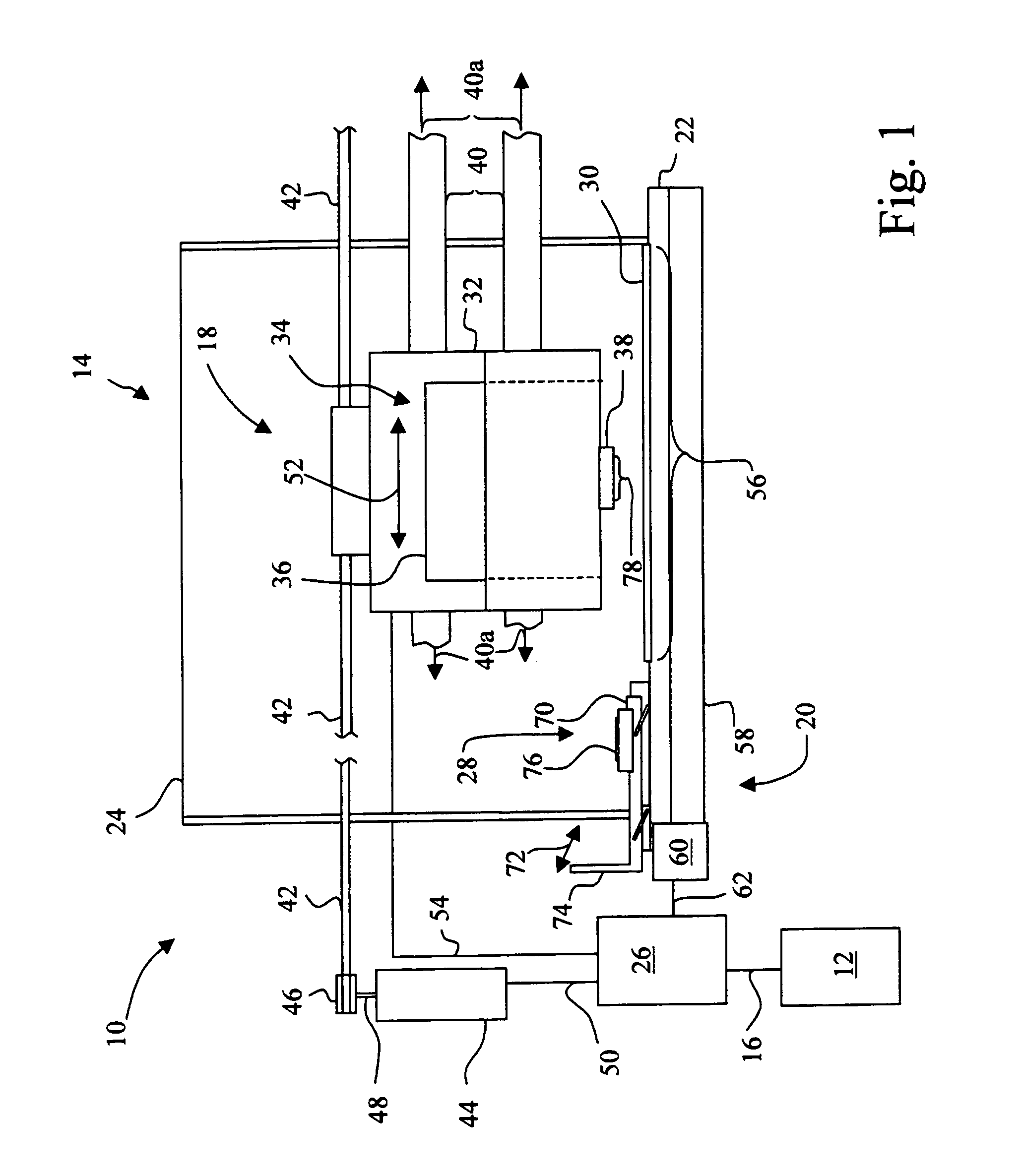
[0021]Referring now to the drawings and more particularly to FIG. 1, there is shown an imaging system 10 employing an embodiment of the present invention. Imaging system 10 includes a computer 12 and an imaging apparatus in the form of an ink jet printer 14. Ink jet printer 14 may, for example, be used as the print engine in a multifunction device, such as a device that also includes faxing and copying capabilities. Computer 12 is communicatively coupled to ink jet printer 14 by way of communications link 16. Communications link 16 may be, for example, a wired connection, an optical connection, such as an optical or r.f. connection, or a network connection, such as an Ethernet Local Area Network.

[0022]Computer 12 is typical of that known in the art, and includes a monitor to display graphics or text, an input device such as a keyboard and / or mouse, a microprocessor and associated memory, such as random access memory (RAM), read only memory (ROM) and a mass storage device, such as CD...


PUM


Abstract

A printhead capping assembly includes a cap holder and a printhead cap. The cap holder defines a cavity and a vent exit. The printhead cap has a base and a lip portion extending from the base. The lip portion defines an open interior region. The base is inserted into the cavity of the cap holder. The base includes a serpentine channel extending from the open interior region to the vent exit of the cap holder.

Description

BACKGROUND OF THE INVENTION[0001]1. Field of the Invention[0002]The present invention relates to printhead maintenance in an ink jet printer, and, more particularly, to a printhead capping assembly.[0003]2. Description of the Related Art[0004]Ink jet printers form an image on a print medium by selectively ejecting ink from one or more of a plurality of ink jet nozzles formed in a nozzle plate of an ink jet printhead. In order to maintain the printhead at an acceptable level of performance, ink jet printers typically include a maintenance station for performing scheduled maintenance operations and for providing a sealed environment for the printhead nozzle plate during periods of non-use.[0005]One example of a maintenance station includes a movable maintenance sled including a printhead wiper and a printhead cap. The printhead wiper includes a blade edge for engaging the printhead nozzle plate to remove waste ink and contaminants that have accumulated on the printhead nozzle plate du...

Claims


Application Information

Patent Timeline
Patent Type & Authority Patents(United States)
IPC IPC(8): B41J2/165
CPCB41J2/16508
Inventor ALDRICH, CHARLES STANLEYEHLERT, JEFFREY RAYJOHNSON, MARTIN ALANLABAR, DANIEL ROBERTMEADOWS, ROBERT MICHAELNARO, BRIAN ANDREW
Owner FUNAI ELECTRIC CO LTD
Why Eureka
Try Eureka