Silicon-based miniature loop heat pipe cooler

A loop heat pipe and cooler technology, applied in the field of silicon-based micro loop heat pipe coolers, can solve the problems of increased heat load and uneven heating of microelectronic chips, achieve safe and reliable working performance, reduce working medium flow resistance, The effect of increasing the heat transfer limit

Inactive Publication Date: 2015-03-11
JIANGSU UNIV
View PDF7 Cites 8 Cited by
  • Summary
  • Abstract
  • Description
  • Claims
  • Application Information

AI Technical Summary

Problems solved by technology

[0004] In view of the fact that the existing LPH heat dissipation technology is difficult to effectively solve the problem that the heat load of the microelectronic chip increases rapidly and causes local "hot spots" on the surface due to uneven heat generation, the present invention provides a silicon-based micro-loop heat pipe cooler, which can Effectively reduce the temperature of the "hot spot" part of the chip, improve the heat dissipation and cooling efficiency, combine the characteristics of LPH and the advantages of micro-scale heat transfer to enhance the heat transfer and temperature control ability, and make the working performance of the microelectronic chip safer and more reliable

Method used


Image

  • Silicon-based miniature loop heat pipe cooler
  • Silicon-based miniature loop heat pipe cooler
  • Silicon-based miniature loop heat pipe cooler

Examples


Embodiment 1

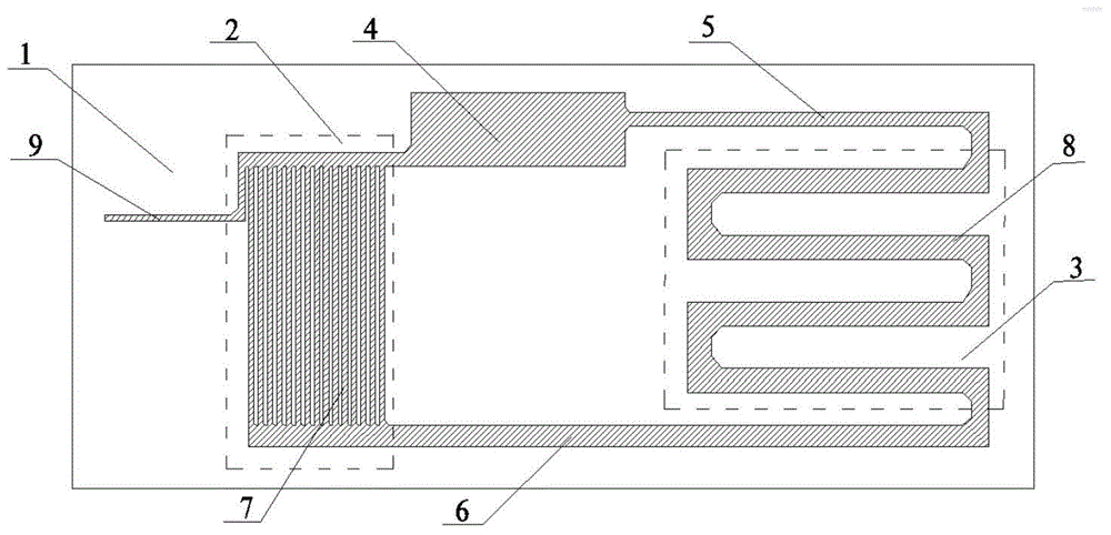
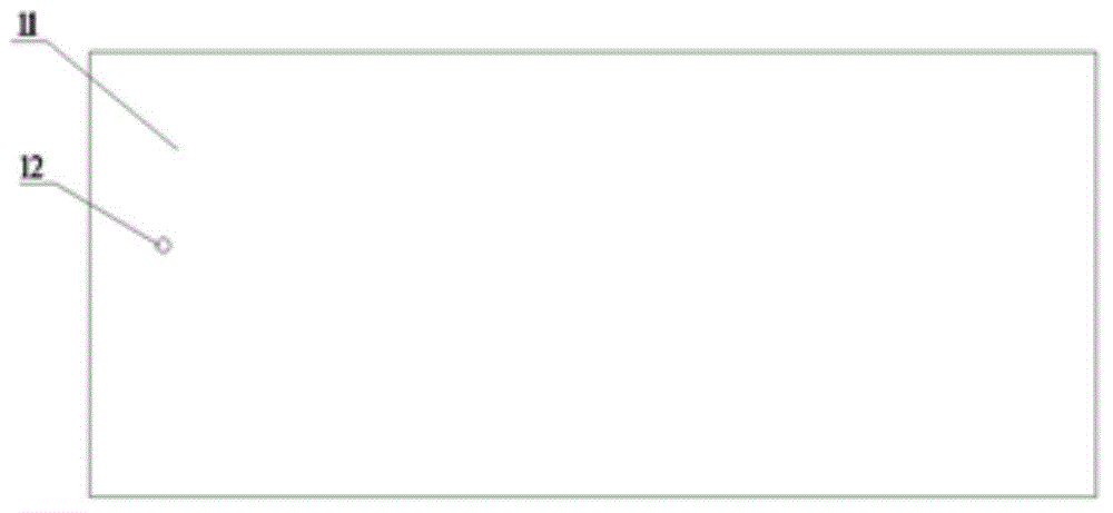
[0030] A silicon-based micro-loop heat pipe cooler includes a semiconductor silicon chip 1 and a heat-resistant borosilicate glass chip 11 bonded together, and the semiconductor silicon chip 1 can be integrated with a semiconductor microelectronic chip. Such as figure 1 As shown, the surface of the silicon wafer 1 in contact with the borosilicate glass wafer 11 is etched with an evaporator 2, a condenser 3, a liquid compensator 4, a liquid phase channel 5, a vapor phase channel 6 and vacuum / injection Liquid channel 9. Both ends of the evaporator 2 and the condenser 3 are respectively connected through a liquid phase channel 5 and a vapor phase channel 6 to form a closed loop. The liquid storage chamber 4 is located on the liquid phase channel 5 , close to the evaporator 2 . The condensation serpentine channel 8 is composed of several U-shaped channels arranged at equal intervals and connected. The number of U-shaped channels is suitable to be 2-8, and the channel hydraulic ...

Embodiment 2

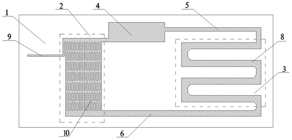
[0035] Such as figure 2 As shown, the difference from Embodiment 1 is the tiny channel structure of the evaporator 2 . In this embodiment, the micro-channel structure of the evaporator 2 is composed of micro-rib array capillary structures 10 . The micro-rib array capillary structure 10 is composed of a plurality of micro-ribs arranged in an array and etched on the silicon wafer, and micro-channels are formed between the micro-ribs. The width of the micro-ribs is 100-300 μm, the length is 400-1200 μm, the distance between two columns of micro-ribs is 50-300 μm, and the distance between two rows of micro-ribs is 50-300 μm. The cross-section of the micro-ribs is rectangular, triangular or circular, and the array arrangement of the micro-ribs is straight or forked.

[0036] Specifically, in this embodiment, the microrib array capillary structure 10 is arrayed in a straight line, including 15 rows arranged horizontally and 7 rows vertically, the width of the rectangular microrib...

Embodiment 3

[0038] On the basis of Embodiment 1 or Embodiment 2, in this embodiment, the cross-sectional dimensions of the liquid phase channel 5 and the vapor phase channel 6 change linearly along the channel direction, wherein the liquid phase channel 5 is from the liquid compensator 4 to the direction of the condenser 3 decreases linearly, while the vapor phase channel 6 increases linearly from the evaporator 2 to the condenser 3. The cross-sectional area of ​​the liquid phase channel 5 decreases linearly from the liquid storage chamber 4 to the condenser 3, the channel width decreases from 600 μm to 300 μm, and the corresponding channel hydraulic diameter decreases from 300 μm to 240 μm; while the width of the vapor phase channel 6 is reduced by The increase from 500 μm to 1000 μm corresponds to an increase in the hydraulic diameter of the channel from 285.7 μm to 333.3 μm. After the above adjustments, it is beneficial to enhance the spontaneous capillary movement effect of the vapor-...


PUM


Abstract

The invention provides a silicon-based miniature loop heat pipe cooler, which comprises a semiconductor silicon wafer and a heat-resisting borosilicate glass sheet which are bonded together; an evaporator, a condenser, a liquid compensator, a liquid-phase channel, a vapor-phase channel and a vacuumizing/liquid injection micro-channel are etched on the surface, in contact with the borosilicate glass sheet, of the silicon wafer; two ends of the evaporator and two ends of the condenser are connected respectively through the liquid-phase channel and the vapor-phase channel to form a closed loop; a liquid storage cavity is arranged on the liquid-phase channel; the evaporator comprises small conduits; the condenser comprises a condensation serpentine channel; the evaporator is communicated with the vacuumizing/liquid injection micro-channel; a vacuumizing/liquid injection hole which can be communicated with the vacuumizing/liquid injection micro-channel is processed in the borosilicate glass sheet. The silicon-based miniature loop heat pipe cooler provided by the invention can be directly integrated with a semiconductor microelectronic chip, and therefore the temperature and the temperature gradient of the chip are effectively reduced, the 'hotspot' problem caused by local high heat flow is reduced and weakened, and the safe and reliable operation of the chip is ensured.

Description

technical field [0001] The invention belongs to the field of temperature control of microelectronic chips, in particular to a silicon-based miniature loop heat pipe cooler. Background technique [0002] In recent years, with the development trend of high performance and miniaturization of various electronic devices and equipment (such as computer chips, etc.), their working heat load will increase rapidly and cause excessive heat generation, which will seriously affect the electronic devices. performance and safety reliability. At the same time, the uneven heating of the microelectronic chip itself will generate "hot spots" on the local surface, and its existence is considered to be the key reason for the "thermal failure" of the chip and the threat to system security. In view of the small cooling space and difficult heat dissipation of microelectronic chips, in order to control the chip temperature at a safe level, improve its temperature uniformity, and reduce local "hot ...

Claims


Application Information

Patent Timeline
Patent Type & Authority Applications(China)
IPC IPC(8): F28D15/04
Inventor 孙芹屈健王谦韩新月王颖泽
Owner JIANGSU UNIV
Why Eureka
Try Eureka