Surgical knife safety handle

a knife and handle technology, applied in the field of surgical knife safety handles, can solve the problems of accidental cuts of hospital personnel, blades may be exposed to operating suite personnel, and not paying close attention to scalpels, so as to reduce the chance of cuts or nicks during handling or disposal.

Inactive Publication Date: 2006-04-04
BEAVER VISITEC INT US
View PDF51 Cites 54 Cited by
  • Summary
  • Abstract
  • Description
  • Claims
  • Application Information

AI Technical Summary

Benefits of technology

[0012]It is therefore an object of this invention to provide a device and method that may be used to shield and protect a sharp blade, such as a scalpel, and minimize the chances of cuts or nicks during handling or disposal.

Problems solved by technology

Unfortunately, accidental cuts of hospital personnel do occur for a variety of reasons.
For example, because the physician and assistant are concentrating on the patient and the procedure being performed on the patient, they may not pay close attention to the scalpels.
The assistant may put the used scalpels in an inappropriate location or, even if the used scalpels are placed on the proper tray, the blade may be exposed to the operating suite personnel.
In these situations, the operating suite personnel may inadvertently come into contact with the blade as they move around the patient during the procedure and be cut or nicked by the exposed blade.
Other hospital personnel may also come into contact with such blades and may also be cut or nicked.
However, during cleanup of the operating suite, the used blades may be exposed prior to their placement in the appropriate sharps container.
If hospital personnel are not paying close attention to their activities or, if the exposed blades are hidden from view because they are buried in a pile of other devices or hospital linen, these hospital personnel may come into contact with the sharp cutting surface of the blade and be cut or nicked.
Cuts and nicks from blades are uncomfortable and distracting at best.
In addition, such cuts and nicks from used blades may result in blood or body fluid exposure which can result in the spread of infectious diseases between the patient and hospital personnel.
Unfortunately, these designs are deficient because they tend to be cumbersome, difficult to use, may cause unwanted shielding or exposure of the blade prior to the need for such shielding or exposure.
Also, such devices may require considerable attention by the user to shield or expose the blade.
Additionally, the shield may distort the handle outline when retracted, making the handle difficult to hold or control.
Such concerns also apply in cases in which the user is required to hold the retracted shield as a grip, allowing any movement between shield and handle to possibly result in unwanted movement of the blade.

Method used


Image

  • Surgical knife safety handle
  • Surgical knife safety handle
  • Surgical knife safety handle

Examples


first embodiment

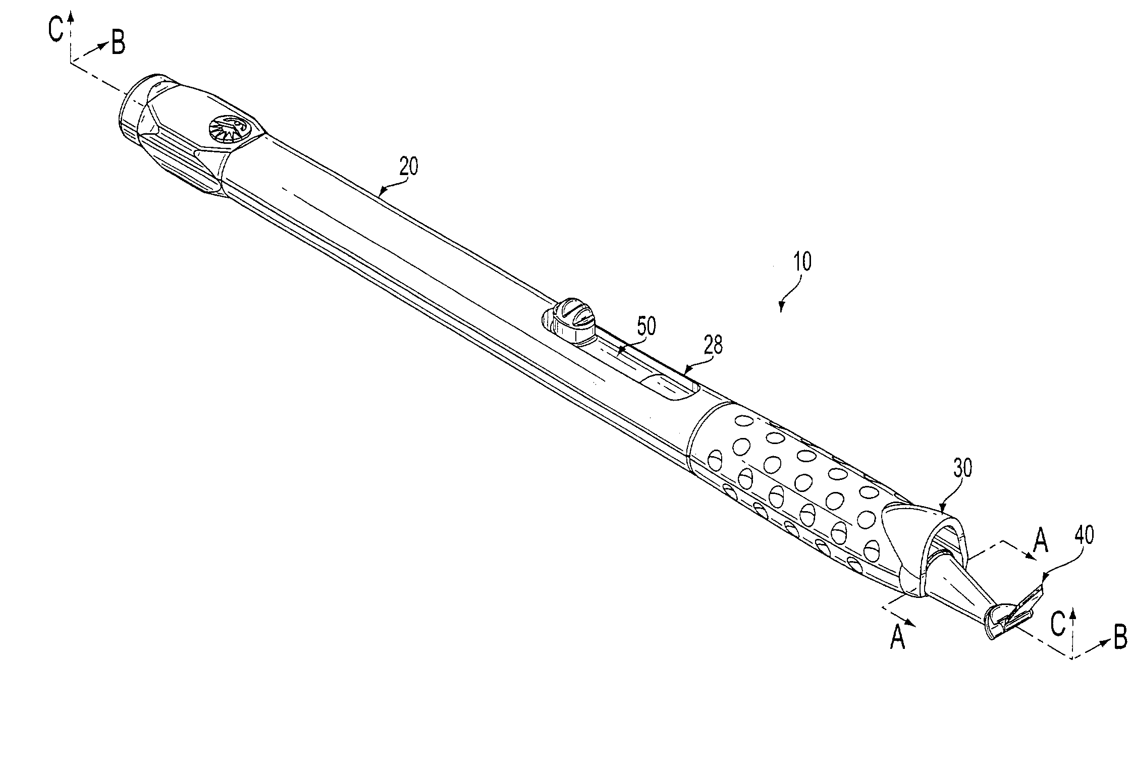
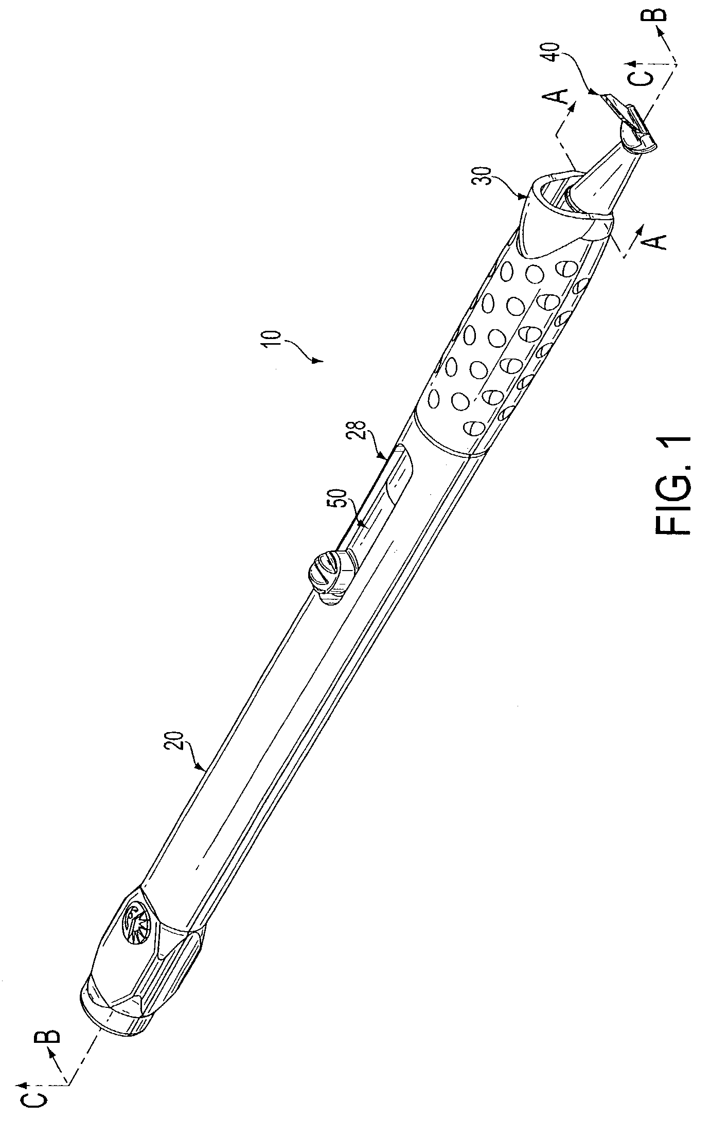
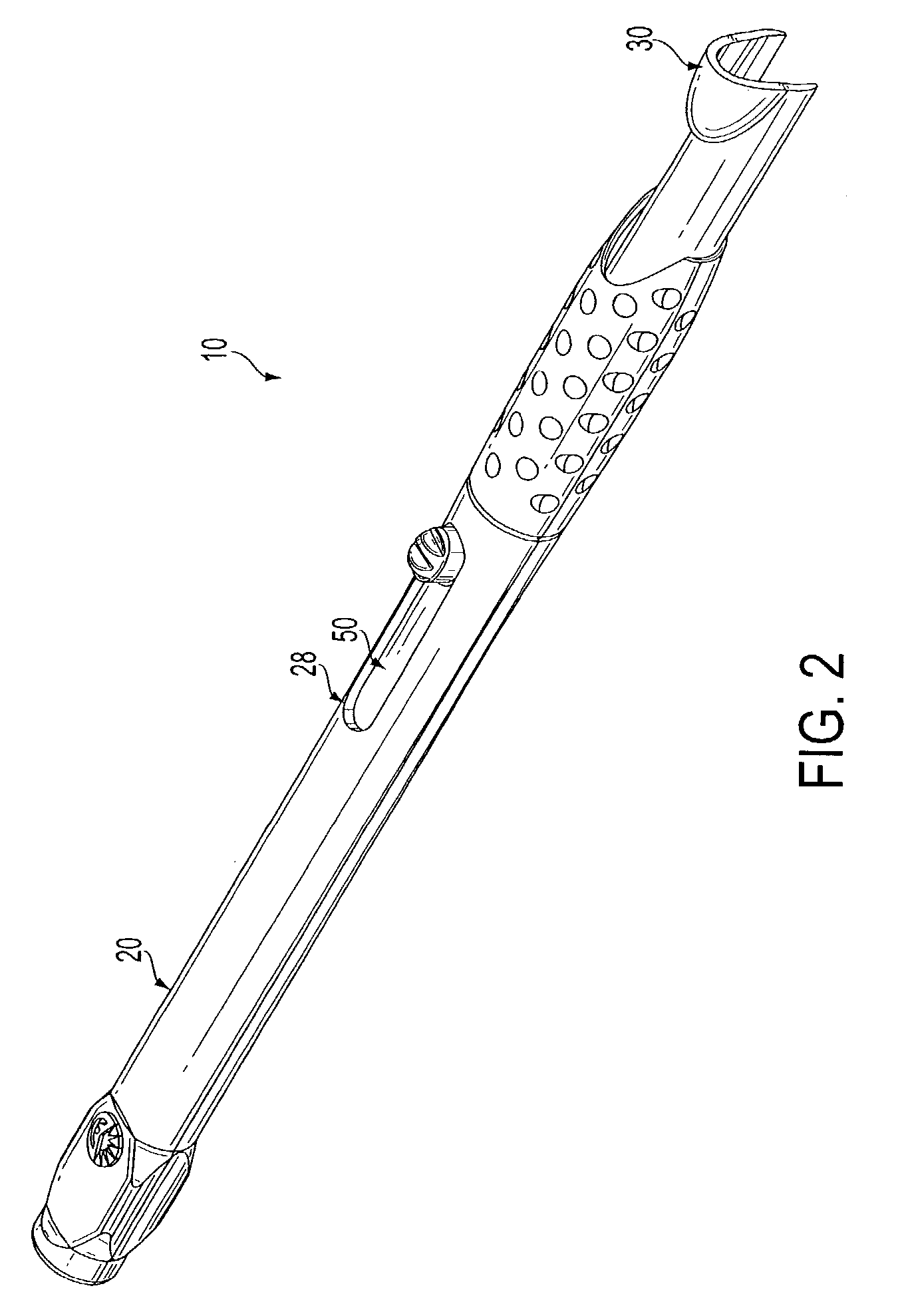
[0048]In the present invention, the guard 30 does not have a fully circular cross section at the distal end due to the molded attachment of the holder 26 to the lower body contour wall 24. This feature ensures the user is allowed to firmly grip a surface that is singularly molded with the blade holder 26. This presents a more positive grip which is less susceptible to unwanted blade or gripping surface movements due to tolerances between the guard 30 and each body contour wall 22 and 24. The expanded distal end of the guard 30 which remains external to the body 20 when fully retracted however, is rigid enough to provide additional control and blade orientation with one or more fingers of the user if so desired during use.

[0049]FIGS. 5A–5E, 6 and 7 show additional details of the guard positioning mechanism 50 and the guard 30. FIG. 5A illustrates the engagement between the guard positioning mechanism and the guard, and FIGS. 6 and 7 illustrate an enlarged cross-sectional view of the ...

second embodiment

[0064]FIG. 10 is an exploded perspective view of the present invention. The view of FIG. 10 includes a first and second body contour wall 122 and 124, formed to assemble as a handle body 120 and define a substantially hollow chamber within the body 120 to house a concealable portion of the guard 130. The first and second body contour walls 122 and 124 each provide a recess, which when assembled, creates a slot 128 extending rearward from the distal end and accessing the chamber to allow protrusion of a raised operator control 158 for the guard 130. The distal end of the first and second body contour wall 122 and 124 also includes an outer surface having a dimpled texture, extending from the distal end to a point slightly before the midpoint of the access slot 128. Additionally, as shown FIGS. 8 and 9, the outer circumference surface area of an exposed portion of guard 130 also includes a dimpled texture, such that when fully retracted, the dimpled texture surface area is unbroken ab...


PUM


Abstract

The present device and method includes a handle, a blade connected to the handle, and a guard slidably mounted partially within the handle for sliding movement between a retracted position in which the blade is exposed for use, and an extended position for covering the sharp cutting edge of the blade. In the retracted position, an exposed guard radius is provided at the distal end of the handle to allow improved handle control and blade orientation. The exposed guard radius is positioned to allow the user to firmly grip a large distal handle portion which is molded as a single piece with the blade holder, preventing unwanted blade or handle movement due to guard mechanism tolerances. A leaf spring and detent is provided to fix the guard in the extended and retracted position, and provide slight resistance during movement between each position. Additionally, an antitravel mechanism is incorporated in the guard to prevent accidental retraction from the fully extended position.

Description

FIELD OF THE INVENTION[0001]The present invention relates to a system and method for a surgical knife safety handle, for both ophthalmic and non-ophthalmic applications, having a movable guard that can be retracted to expose the blade when in use, and that can be extended to cover the blade when not in use, and including a pushback prevention mechanism to ensure the blade is covered until manually exposed.BACKGROUND OF THE INVENTION[0002]In various surgical procedures, the physician typically has to make an incision in the patient in order to remove unwanted tissue, repair damaged tissue, or implant a device to improve the patient's well being. In certain cases, all three of these activities, or a combination thereof, must be done in a single procedure. For example, in cataract surgery, the physician removes the natural lens that has been clouded by a cataract from the patient's eye and replaces it with an artificial lens that will improve the patient's eyesight. In order to perform...

Claims


Application Information

Patent Timeline
Patent Type & Authority Patents(United States)
IPC IPC(8): A61B17/32A61B19/00A61F9/013
CPCA61B17/3211A61F9/0133A61B2019/4805A61B2017/32113A61B2090/0801
Inventor MORAWSKI, MICHAEL J.COTE, DANA M.THRAILKILL, PATRICK T.SEEBAUER, DAVID S.RAJASEKARAN, MOHAN
Owner BEAVER VISITEC INT US
Why Eureka
Try Eureka