Prismatic sealed battery module

a battery module and sealed technology, applied in the direction of cell components, flat cell grouping, sustainable manufacturing/processing, etc., can solve the problems of large number of constitution parts, undesirable increase in cost, and difficulty in improving power output and service life characteristics of rechargeable battery modules, so as to reduce losses

Inactive Publication Date: 2006-04-04
PANASONIC CORP +1
View PDF14 Cites 7 Cited by
  • Summary
  • Abstract
  • Description
  • Claims
  • Application Information

AI Technical Summary

Benefits of technology

[0012]The present invention has been devised in light of the above-mentioned problems with the conventional art, and accordingly an object of the present invention is to provide a prismatic sealed battery module in which connection resistance between an electrode plate group and an external terminal is suppressed to reduce a loss induced by electrical connection resistance.

Problems solved by technology

In this conventional construction, due to the complexity of interconnection between the cells, a large number of constitution parts are required.
This leads to an undesirable increase in the cost.
In addition, occurrence of unduly large part resistance makes it difficult to improve power output and service life characteristics in the rechargeable battery module.
Consequently, the length of the entire current-carrying path becomes unduly long, and also the connection resistance is increased because of the necessity of energizing a portion having a small sectional area, giving rise to a-great loss induced by electrical connection resistance.
Another problems with the construction are that: since interconnection between the cells 102 is effected by weld-connecting together the front ends of the connecting projections 111 respectively formed at the upper ends of the collector plates 110a and 110b, the connection path must be made to take a detour, resulting in an increase in the length of the connection path; since the weld-connection is made only at one point, the resistance is increased; using the collector plates 110a and 110b leads to an increase in the cost; and the collector plates 110a and 110b are arranged on both sides of the electrode plate group 108, and their upper parts need to be so formed as to extend beyond the upper end of the electrode plate group 108, resulting in an increase in the volume of the battery case 104.

Method used


Image

  • Prismatic sealed battery module
  • Prismatic sealed battery module
  • Prismatic sealed battery module

Examples


first embodiment

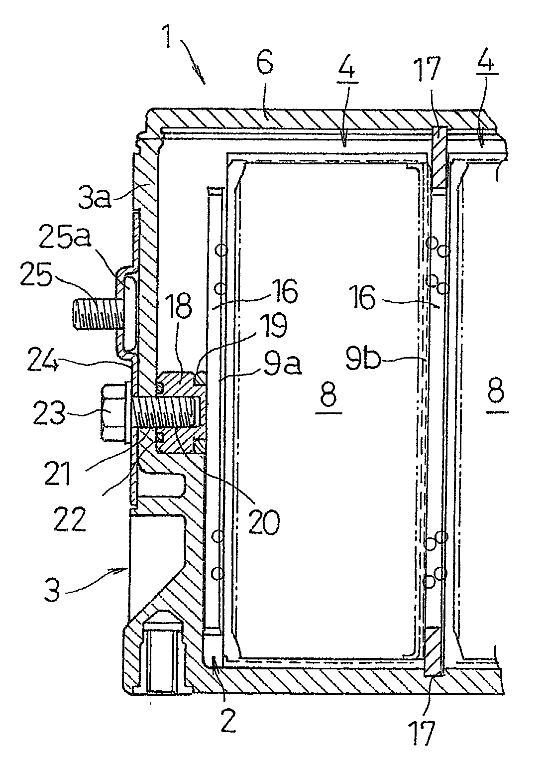
[0022]Hereinafter, a first embodiment of a prismatic sealed battery module according to the present invention will be described with reference to FIGS. 1A and 1B.

[0023]In FIGS. 1A and 1B, a prismatic sealed battery module 1 of the first embodiment incorporates a plurality of cells 2 made of nickel-metal hydride rechargeable batteries. The reference numeral 3 denotes a prismatic battery case, which is formed in the shape of a flat prism by juxtaposing prismatic cell cases 4 with a shorter side surface and a longer side surface, each of whose shorter side surfaces is common to adjacent such cell cases. An upper opening of the prismatic battery case 3 is sealed with an integrally-formed cover 6. The cell 2 is constituted by housing in the cell case 4 an electrolyte and an electrode plate group 8 formed by layering rectangular positive and negative electrode plates with a separator interposed therebetween. Part of the positive and negative electrode plates of the electrode plate group 8...

second embodiment

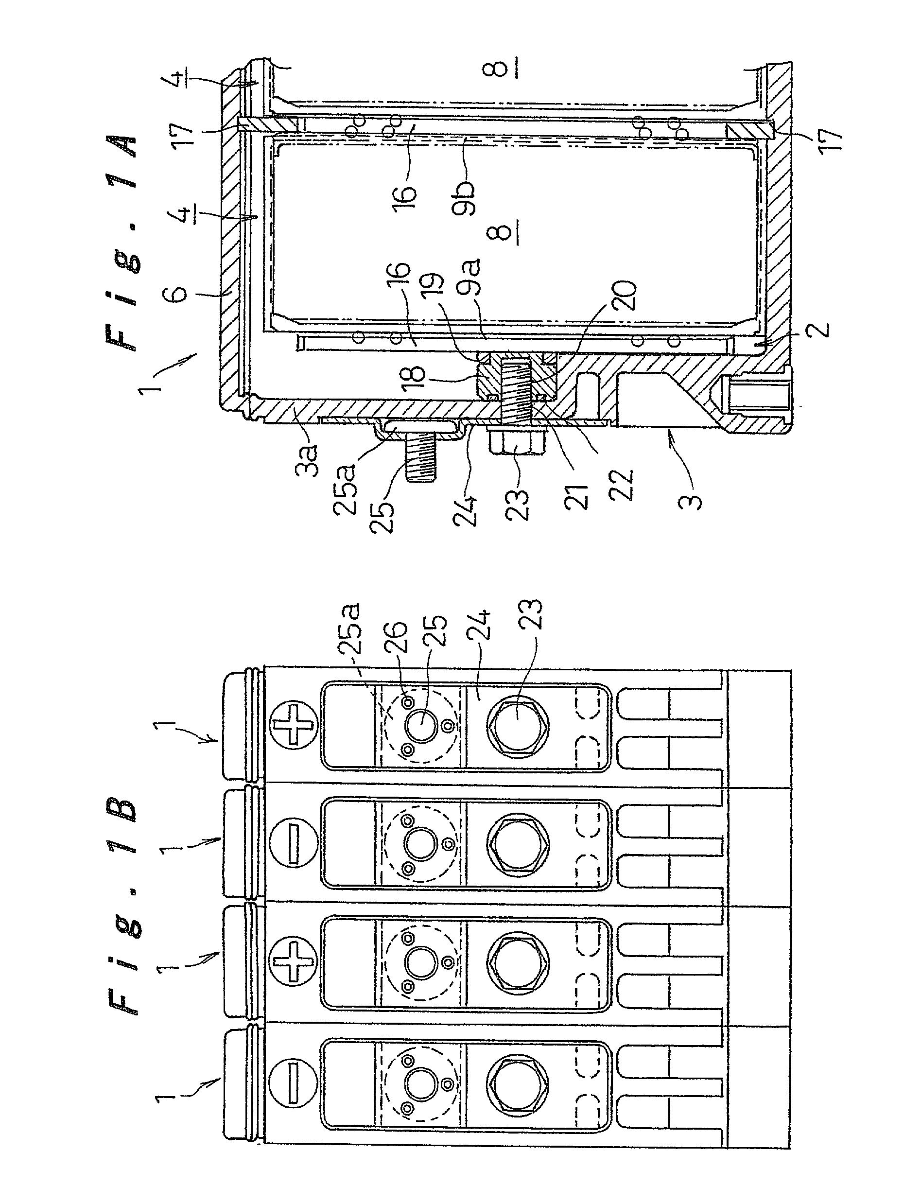
[0033]Next, a second embodiment of the prismatic sealed battery module according to the invention will be described with reference to FIGS. 2A and 2B. Note that, in the descriptions connected to the second embodiment, such elements as are found also in the previous embodiment are identified with the same reference numerals and symbols, and the descriptions thereof will be omitted. That is, only the points of difference will be described below.

[0034]In this embodiment, instead of the externally connecting bolt 23 of the first embodiment, an externally connecting bolt 27 is used that is provided integrally with a concentrically-formed external terminal 25.

[0035]According to the second embodiment, there is no need to additionally provide the connection plate 24, to which the external terminal 25 is fixed, as used in the first embodiment. Thus, the number of constitution parts is reduced, thereby making cost reduction possible.

third embodiment

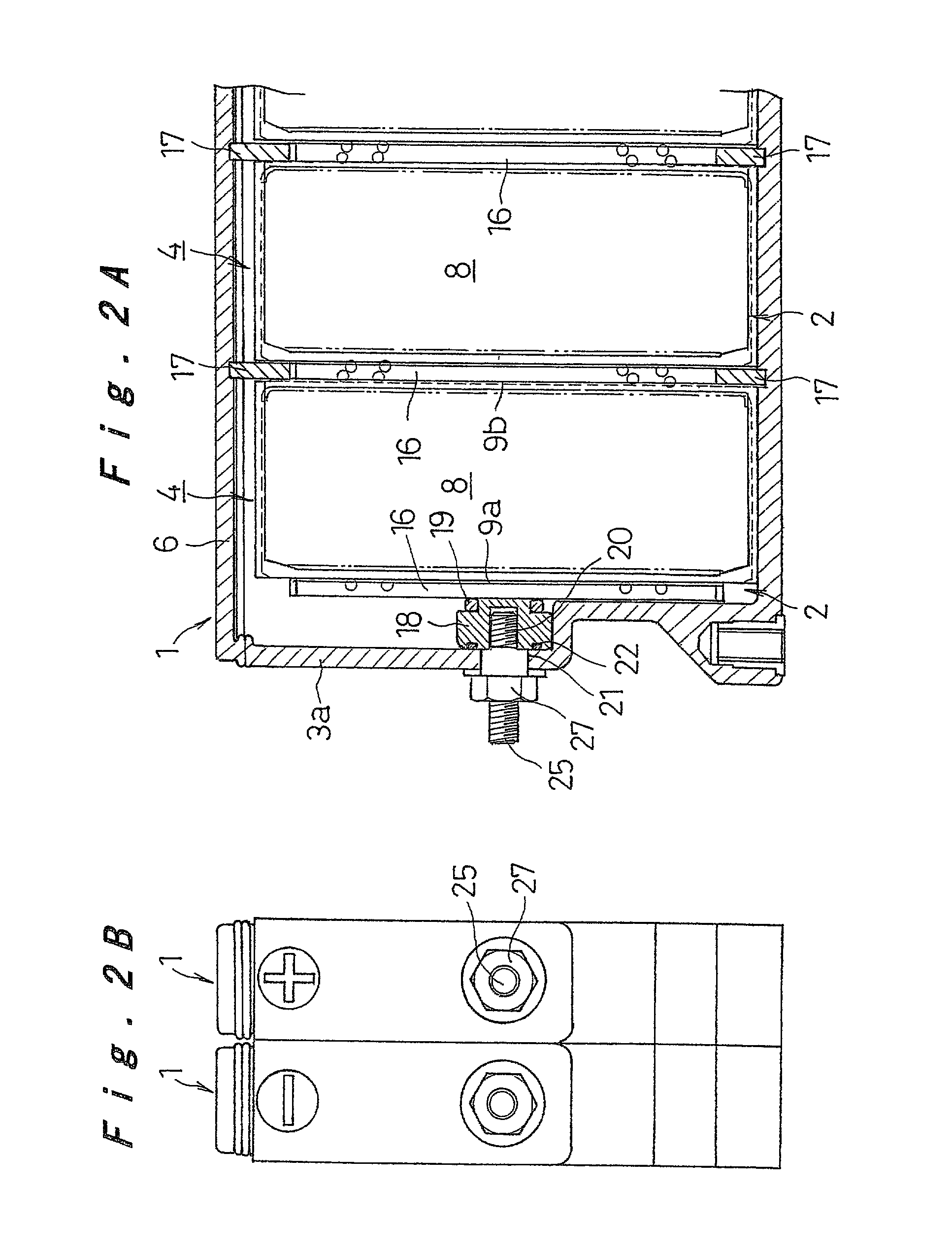
[0036]Next, a third embodiment of the prismatic sealed battery module according to the invention will be described with reference to FIGS. 3A through 4B.

[0037]In this embodiment, instead of the connection plate 24 of the first embodiment with the external terminal 25 attached to it, there is provided an externally connection plate 28 having a substantially L-shaped cross-sectional profile. As shown in FIGS. 3A through 4B, the external connection plate 28 includes a fitting portion 29 and a connecting portion 30 adjoining thereto. The fitting portion 29 makes contact with the outer surface of the side end wall 3a of the prismatic battery case 3, and the connecting portion 30 makes contact with the end of the longer side of the prismatic battery case 3. The fitting portion 29 is fastened to the metal connector 18 with the externally connecting bolt 23. In a bend between the fitting portion 29 and the connecting portion 30 is provided a U-shaped elastic portion 31. As shown in FIG. 4B,...


PUM

PropertyMeasurementUnit
currentaaaaaaaaaa
lengthaaaaaaaaaa
elasticaaaaaaaaaa

Abstract

A prismatic sealed battery module includes: a prismatic battery case; an electrode plate group constituted by alternately layering positive and negative electrode plates with a separator arranged therebetween; and an electrolyte. The positive or negative electrode plates protruding from each end face of the electrode plate group are bonded to a collector member. A metal connector is fixed to the central part of the collector member facing the inner surface of the side end wall of the battery case. The collector member is connected, at the metal connector, to an external terminal using an externally connecting bolt.

Description

[0001]The present disclosure relates to subject matter contained in priority Japanese Patent Application No. 2001-237752, filed on Aug. 6, 2001, the contents of which is herein expressly incorporated by reference in its entirety.BACKGROUND OF THE INVENTION[0002]1. Field of the Invention[0003]The present invention relates to a prismatic sealed battery module, and more particularly to a prismatic sealed battery module which succeeds in reducing connection resistance with respect to an external terminal.[0004]2. Description of Related Art[0005]A conventional rechargeable battery module is typically composed of a plurality of cells connected together to obtain a desired electric power capacity. Such a rechargeable battery module is constructed by stackingly arranging a plurality of prismatic cells such that longer side surfaces of battery cases are arranged opposite each other, followed by placing an end plate outside the battery case of each endmost cell, further followed by binding th...

Claims


Application Information

Patent Timeline
Patent Type & Authority Patents(United States)
IPC IPC(8): H01M2/02H01M2/30H01M10/04H01M10/28H01M50/528H01M50/529H01M50/54H01M50/553H01M50/566
CPCH01M2/22H01M2/24H01M2/30H01M10/281H01M2/266H01M2/0217Y02E60/124H01M10/0413Y02E60/10H01M50/103H01M50/528H01M50/529H01M50/54Y02P70/50H01M50/566H01M50/553
Inventor ASAHINA, TAKASHIHAMADA, SHINJIFUKUDA, SHINSUKEETO, TOYOHIKO
Owner PANASONIC CORP
Why Eureka
Try Eureka