Method and apparatus including in-resonator imaging lens for improving resolution of a resonator-enhanced optical system

a resonator-enhanced optical system and imaging lens technology, applied in the field of optical systems, can solve the problems of limited resolution improvement that may be obtained in optical measurement systems, optical storage and retrieval systems, other optical systems, etc., and achieve the effect of improving resolution and improving resolution in optical systems

Inactive Publication Date: 2006-04-04
XYRATEX CORP
View PDF5 Cites 14 Cited by
  • Summary
  • Abstract
  • Description
  • Claims
  • Application Information

AI Technical Summary

Benefits of technology

[0008]The foregoing objectives are achieved in an improved optical resonator apparatus and optical system having improved resolution performance along with a method for improving resolution in an optical system. The optical system includes a resonator positioned within a pathway of a measurement beam of the optical system. The resonator includes at least one imaging lens for imaging a point or area of one of the reflective surfaces of the resonator on to a point or area of a second reflective surface. The second reflective surface may be one of the resonator (resonant) surfaces, or the second reflective surface may be an intermediary surface and the resonance may be supported with respect to a single reflective surface of the resonator imaged onto itself.
[0009]Inclusion of the lens(es) reduces the optical imaging distance of the resonator to zero by imaging the two mirrors onto each other, while the propagation distance can be any chosen value. Reducing the optical imaging distance to zero improves the performance of the resonator by essentially eliminating the divergence between the multiple internal reflections.

Problems solved by technology

Optical measurement systems, optical storage and retrieval systems and other optical systems may be limited by many factors, including effective detector and illumination resolution.
While incorporation of a resonator within an optical system can provide an improved resolution due to reduction in illumination beam size and / or detection sensitivity of the system, there are limitations on the resolution improvement that may be obtained due to divergence and losses at each internal reflection.
However, due to the finite non-zero propagation distance within the resonator caused by microscopic surface variation on the mirrors, as well as by diffraction effects, the internal reflections will deviate from the ideal resonator geometrical optics model of both linear and perpendicular propagation between the mirrors.

Method used


Image

  • Method and apparatus including in-resonator imaging lens for improving resolution of a resonator-enhanced optical system
  • Method and apparatus including in-resonator imaging lens for improving resolution of a resonator-enhanced optical system
  • Method and apparatus including in-resonator imaging lens for improving resolution of a resonator-enhanced optical system

Examples


Embodiment Construction

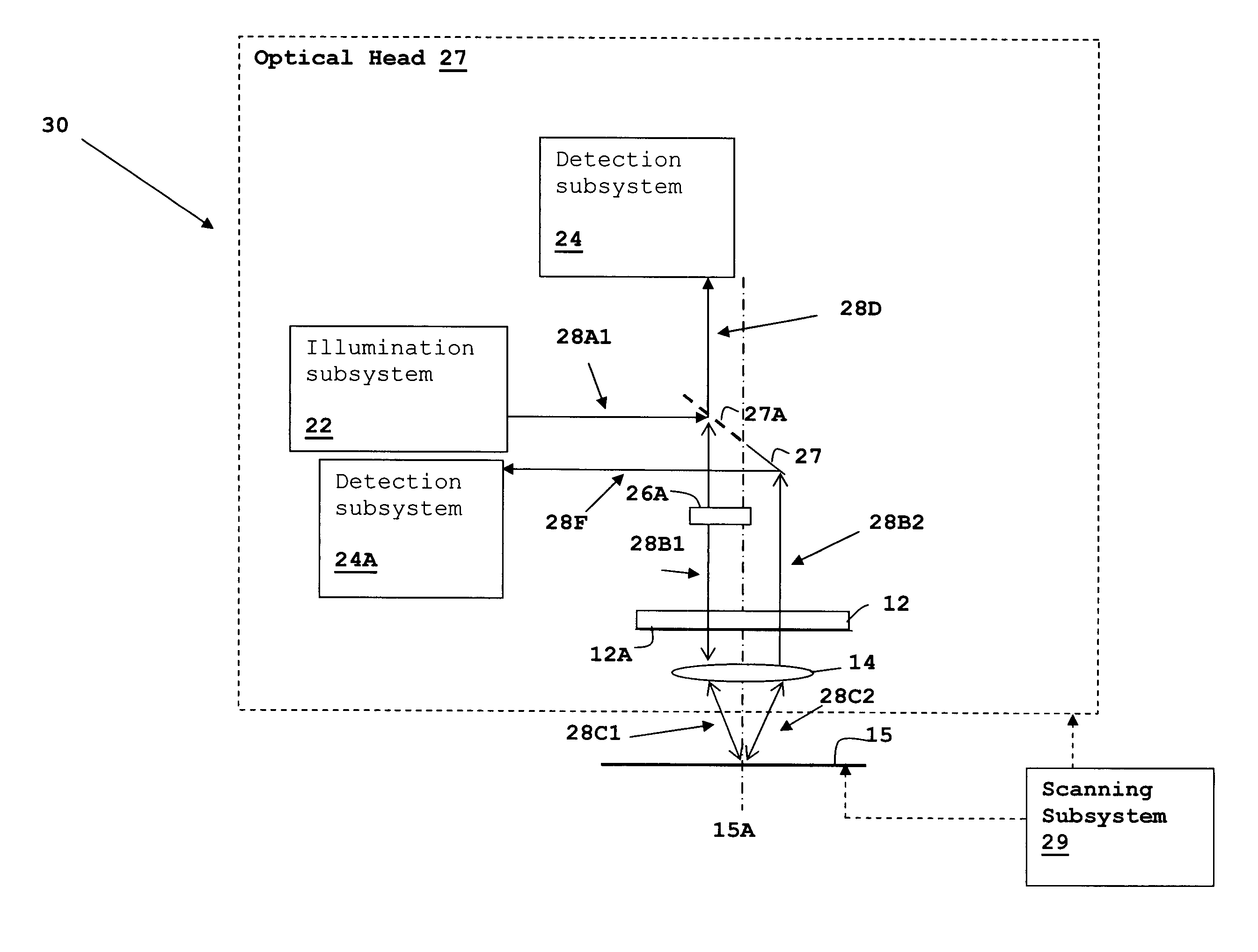
[0019]The above-incorporated patent applications describe various resonator-enhanced optical systems, such as optical storage data and retrieval systems having improved data density, optical measurement systems having improved resolution and contrast, and optical systems having improved detector phase / amplitude slope characteristics controlled over portions of the detector response. The above-recited improvements are developed by placement and tuning of resonators within the optical paths of the associated systems.

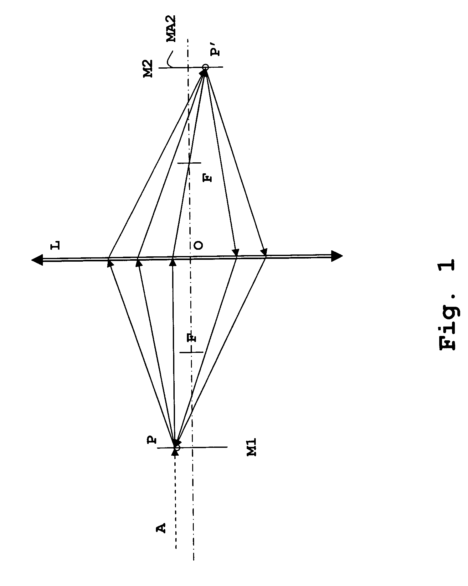
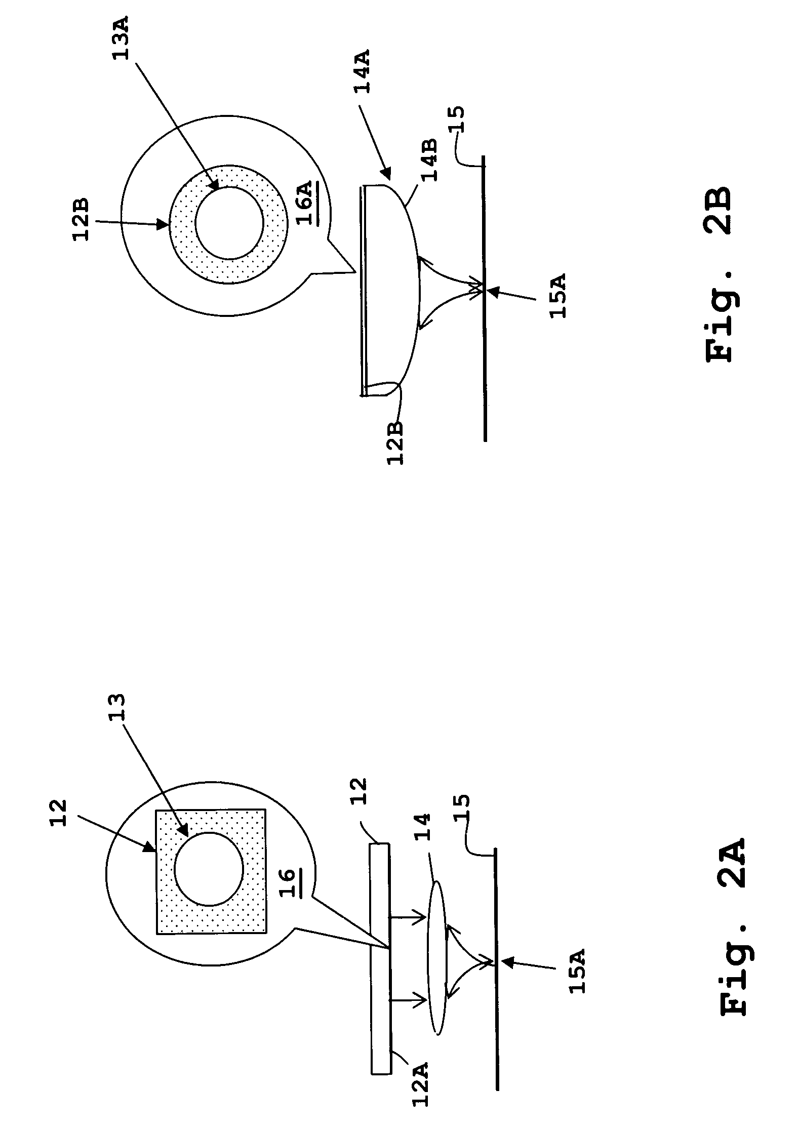
[0020]The present invention concerns a method and resonator apparatus that further improve performance of a resonator-enhanced optical system by incorporating one or more imaging lenses within the resonator, causing the resonance at a single point (in practice, a very small area) or region on one or more of the reflective surfaces forming the resonator. The present invention therefore provides an improvement in all of the above-mentioned resonator-enhanced systems, as well...


PUM

PropertyMeasurementUnit
focal lengthaaaaaaaaaa
focal lengthsaaaaaaaaaa
optical path lengthaaaaaaaaaa

Abstract

A method and apparatus including in-resonator imaging lens for improving resolution of a resonator-enhanced optical system provides resolution improvements for optical inspection and measurement systems, optical storage and retrieval systems as well as other optical systems. An imaging lens is incorporated in the resonator to image a point or area of one of the reflective surfaces of the resonator on a point or area of another reflective surface of the resonator. Resonance may be supported between the two surfaces, or with respect to only one surface with the other surface acting as an intermediary reflector. The partially reflective surface or a totally reflective surface may also be incorporated on a planar outside surface of the imaging lens.

Description

RELATED APPLICATIONS[0001]This application is a continuation-in part of U.S. patent applications “OPTICAL STORAGE METHOD AND APPARATUS HAVING ENHANCED RESOLUTION”, Ser. No. 09 / 871,512, filed May 30, 2001 U.S. Pat. No. 6,700,840; “OPTICAL MEASUREMENT AND INSPECTION METHOD AND APPARATUS HAVING ENHANCED OPTICAL PATH DIFFERENCE DETECTION”, Ser. No. 09 / 933,225, filed Aug. 20, 2001 U.S. Pat. No. 6,653,649; and “OPTICAL INSPECTION METHOD AND APPARATUS HAVING AN ENHANCED HEIGHT SENSITIVITY REGION AND ROUGHNESS FILTERING” Ser. No. 10 / 002,425, filed Oct. 23, 2001 U.S. Pat. No. 6,714,295. The specifications of all of the above-listed parent applications are incorporated herein by reference.BACKGROUND OF THE INVENTION[0002]1. Field of the Invention[0003]This invention relates to optical systems, and more specifically, to an optical system incorporating a resonator to enhance the resolution of optical inspection systems and other optical devices.[0004]2. Description of the Related Art[0005]Optic...

Claims


Application Information

Patent Timeline
Patent Type & Authority Patents(United States)
IPC IPC(8): H01J3/14H01J40/14H01J5/16G01B9/02G01N21/57G01N21/88G02B26/00G11B7/09G11B7/135G11B7/24
CPCB82Y10/00G01N21/57G01N21/8806G02B26/001G11B7/24G01B9/02057G01B9/02018G11B7/1362G11B7/0937G01B2290/45G01B2290/25
Inventor CLARK, BRYANBRUNFELD, ANDREI
Owner XYRATEX CORP
Why Eureka
Try Eureka