System for controlling a magnetically levitated rotor

a technology of magnetically levitation and rotor, which is applied in the direction of mechanical energy handling, dynamo-electric components, mechanical apparatus, etc., can solve the problems of reducing the operating life of components, and affecting the operation efficiency of the rotating mass

Inactive Publication Date: 2006-04-04
NAT AERONAUTICS & SPACE ADMINISTATION U S GOVERNMENT AS REPRESENTED BY THE
View PDF7 Cites 35 Cited by
  • Summary
  • Abstract
  • Description
  • Claims
  • Application Information

AI Technical Summary

Benefits of technology

[0009]In accordance with the above objects, and others, the present invention advantageously provides a rotor assembly that is suspended for rotation in magnetic bearings to attain speeds higher than that for conventional bearings (i.e., ball bearings) and in which sufficient clearance is provided to allow magnetically-induced perturbations to cause abaxial rotation as well as nutation of the rotating components in response to software-driven processor commands.
[0010]The present invention provides for the creation of various types of perturbations via software control to investigate the performance of the rotor or rotor assembly under differing conditions.

Problems solved by technology

The fundamental frequency of the vibration, as well as the harmonics thereof, and concomitant force vectors that rapidly change magnitude and direction with each rotation can function as an operational limit on rotational speed and, with time, reduce the operating life of the components.
For example, bearing life can be substantially reduced as a consequence of prolonged vibration and, in some cases, portions of the rotating mass can be subject to fatigue failures.

Method used


Image

  • System for controlling a magnetically levitated rotor
  • System for controlling a magnetically levitated rotor
  • System for controlling a magnetically levitated rotor

Examples


Embodiment Construction

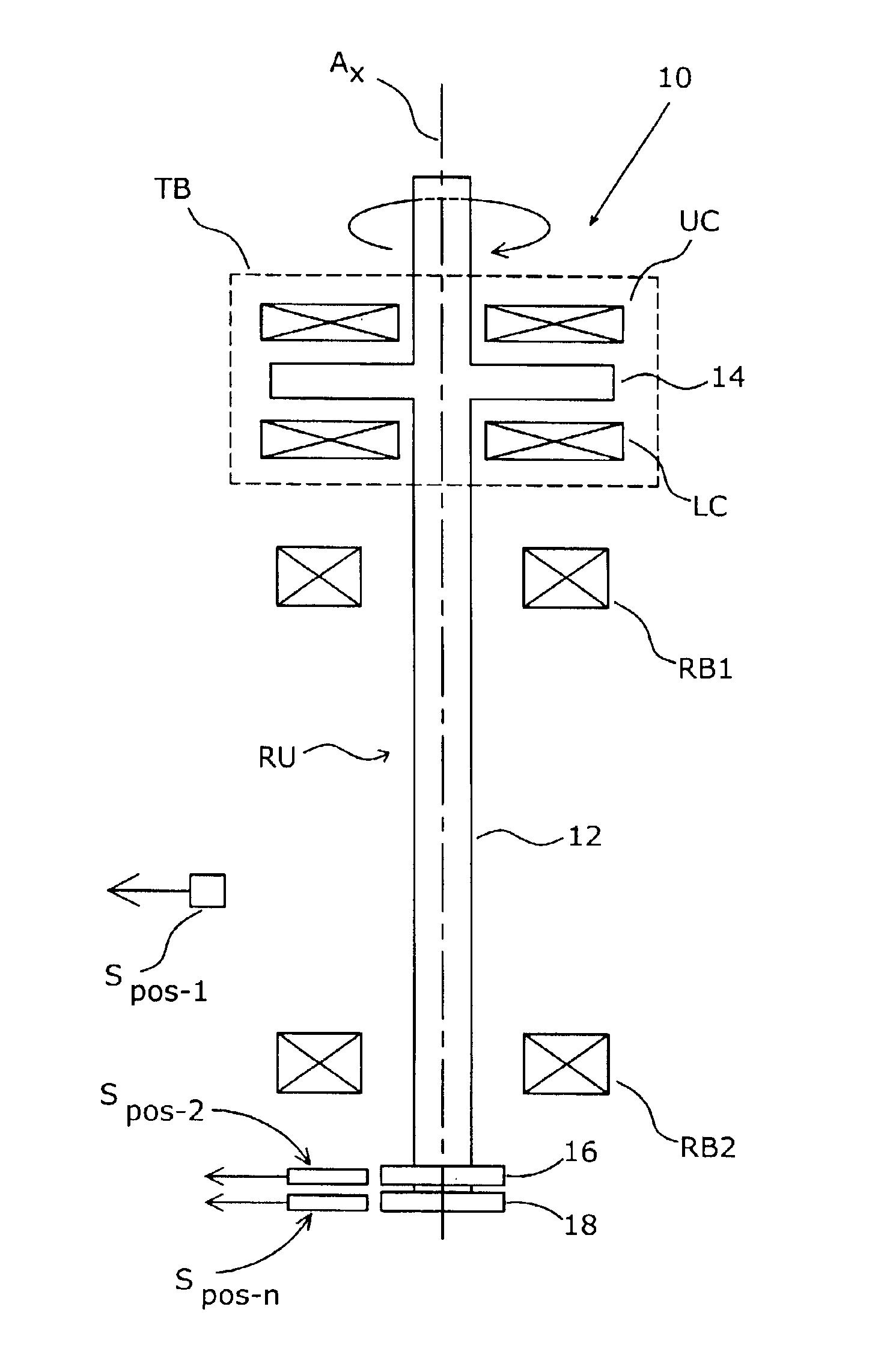
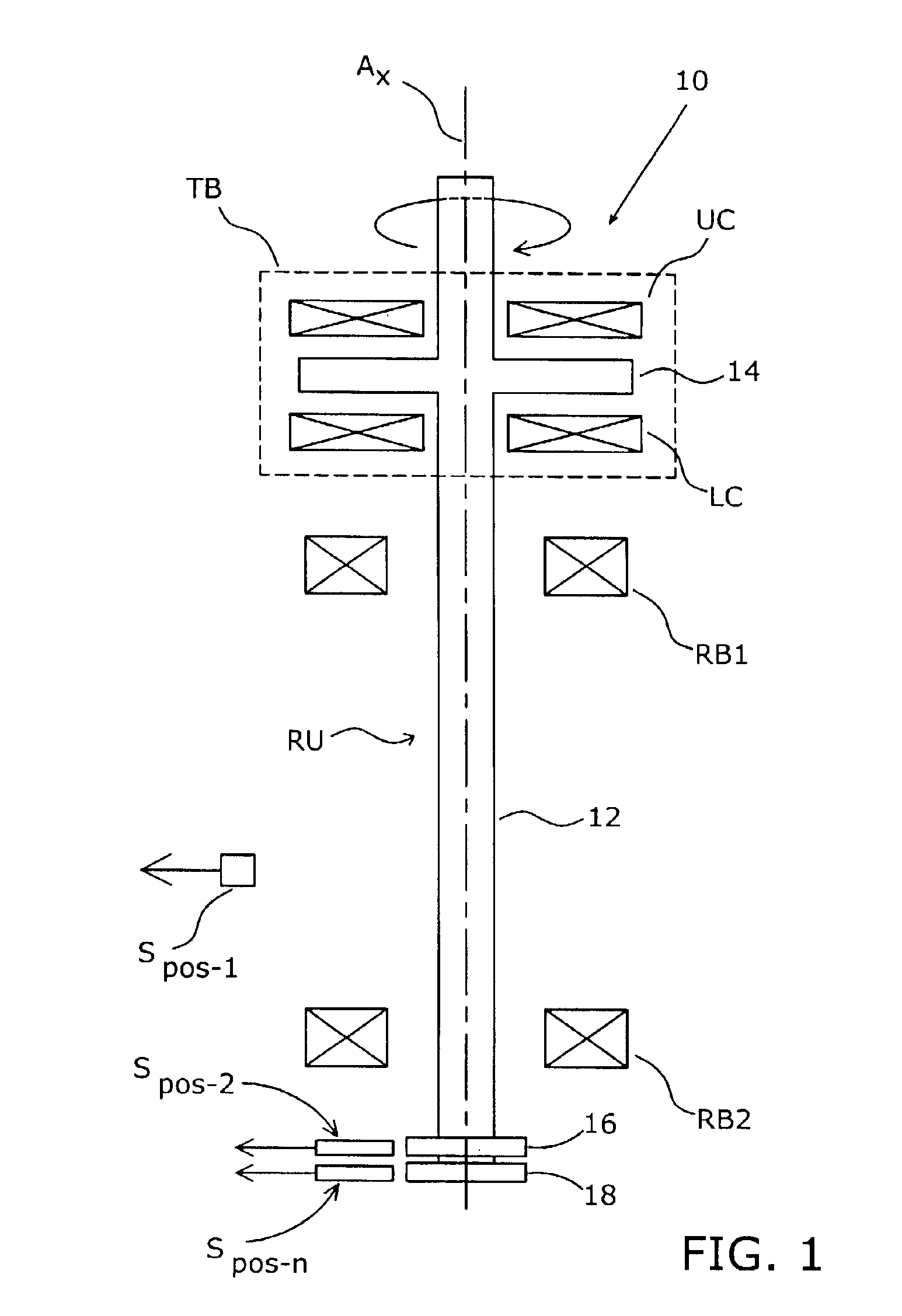
[0025]The present invention is intended for use with rotor systems of the general type shown in FIG. 1 and designated therein generally by the reference character 10. As shown, the rotor system 10 includes a rotor unit RU that is generally aligned in the vertical direction. The rotor unit RU includes a generally cylindrical shaft portion 12 (having a longitudinal axis Ax) and a diametrically-enlarged thrust plate portion 14. Typically, the rotor unit RU is fabricated from separate piece-parts that are joined together to form an assembly, although the rotor unit RU can also be fabricated as a unitary structure.

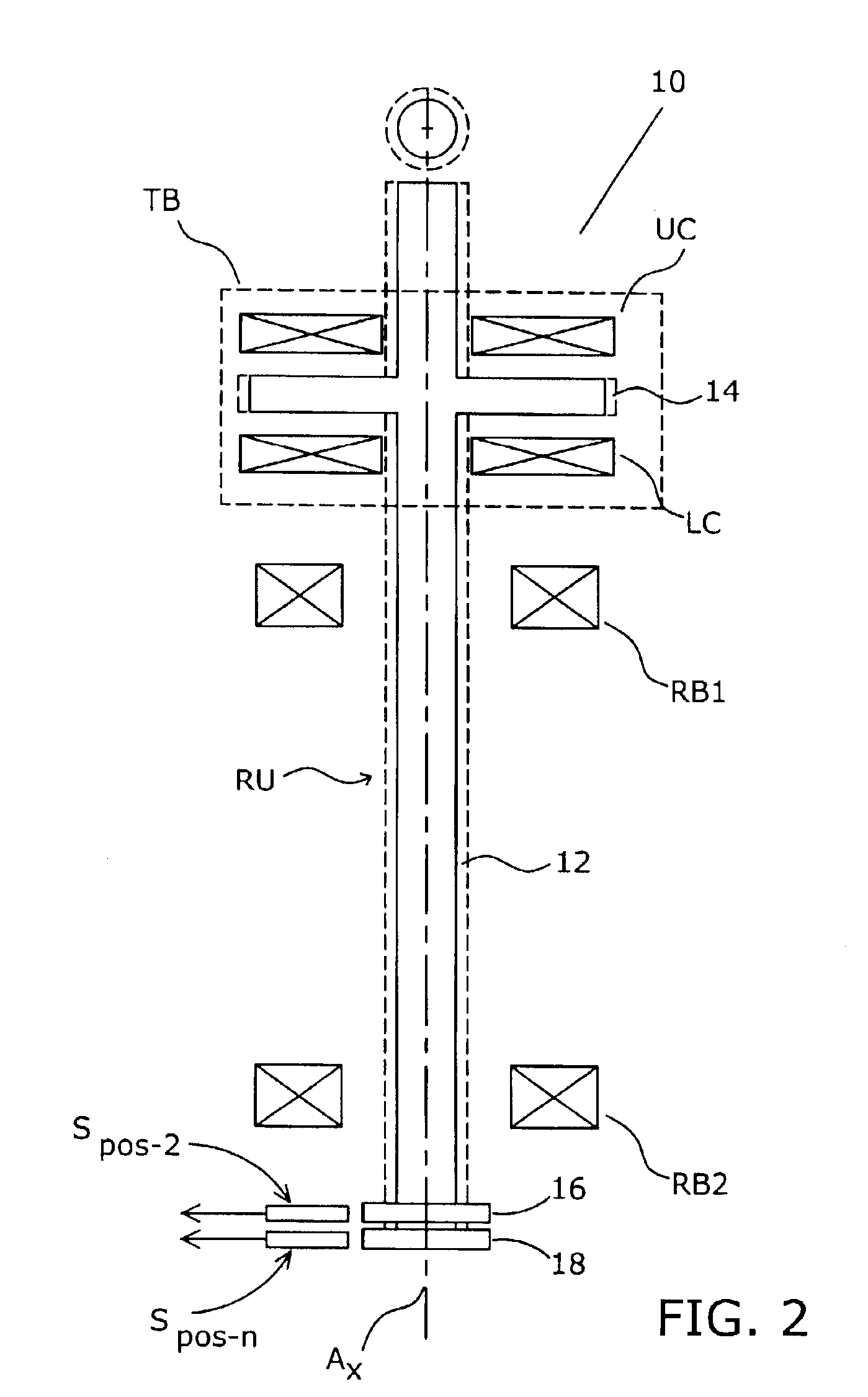
[0026]The rotor unit RU is designed to be received by and magnetically suspended in a set of magnetic bearings that can be controlled to displace the rotor unit RU in various ways, as shown in FIG. 2 through FIG. 5B. The magnetic bearings include a thrust bearing assembly TB that includes an upper coil UC and a lower coil LC located on opposite sides of the trust plate 14 and d...


PUM


Abstract

In a rotor assembly having a rotor supported for rotation by magnetic bearings, a processor controlled by software or firmware controls the generation of force vectors that position the rotor relative to its bearings in a “bounce” mode in which the rotor axis is displaced from the principal axis defined between the bearings and a “tilt” mode in which the rotor axis is tilted or inclined relative to the principal axis. Waveform driven perturbations are introduced to generate force vectors that excite the rotor in either the “bounce” or “tilt” modes.

Description

[0001]This patent application claims the benefit of U.S. Provisional Patent Application Ser. No. 60 / 364,002 filed Mar. 14, 2002, the disclosure of which is incorporated herein by reference.[0002]The invention described herein was made by employees of the United States Government and may be manufactured and used by or for the Government of the United States of America for governmental purposes without the payment of any royalties thereon or therefor.BACKGROUND OF THE INVENTION[0003]The present invention relates to a software-implemented system for controlling the movement of a magnetically supported rotor and, more particularly, to such a software-implemented system for introducing selected perturbations into the movement of the rotor.[0004]Turbomachinery, as a class, typically includes one or more rotor or rotor assemblies mounted on a bearing-supported shaft for rotation about a primary axis. In general, the rotor is subject to radially directed stress as a consequence of shaft rot...

Claims


Application Information

Patent Timeline
Patent Type & Authority Patents(United States)
IPC IPC(8): H02K7/02F16C39/06
CPCF16C32/0442F16C32/0455F16C32/0489
Inventor MORRISON, CARLOS R.
Owner NAT AERONAUTICS & SPACE ADMINISTATION U S GOVERNMENT AS REPRESENTED BY THE
Why Eureka
Try Eureka