Device for operation of a high pressure discharge lamp

a technology for discharge lamps and devices, applied in the direction of electric variable regulation, process and machine control, instruments, etc., can solve the problems of so-called flicker, unstable arc spots, and projections disappearing,

Active Publication Date: 2006-04-04
USHIO DENKI KK
View PDF5 Cites 61 Cited by
  • Summary
  • Abstract
  • Description
  • Claims
  • Application Information

AI Technical Summary

Benefits of technology

[0028]The following effects are achieved by the above described arrangement in accordance with the invention:
[0029]1. Projections are formed on the electrode tips, and a stable arc discharge can be formed by these projections, each acting as the starting point of the discharge. As is disclosed in JP-A-2002-175890 (U.S. Pat. No. 6,713,972 B2), it is not a technology in which projections are eliminated, but projections are actively produced. In this way, an arc is formed, these projections each acting as a discharge starting point. Therefore, there is the action that operation of the discharge lamp can be stabilized.
[0030]2. Formation of superfluous projections besides the projections which act as the arc start point can be prevented. The reason for this is the following:

Problems solved by technology

For example, in JP patent disclosure document 2002-175890, the presence of these projections is regarded as a disadvantage and a technology is presented in which the projections are caused to disappear.
Even if a high pressure discharge lamp (ultra-high pressure mercury lamp) has been operated as the light source of a projector device by the above described technology, the arc spot becomes unstable and so-called flicker occurs to a great degree.

Method used


Image

  • Device for operation of a high pressure discharge lamp
  • Device for operation of a high pressure discharge lamp
  • Device for operation of a high pressure discharge lamp

Examples


Embodiment Construction

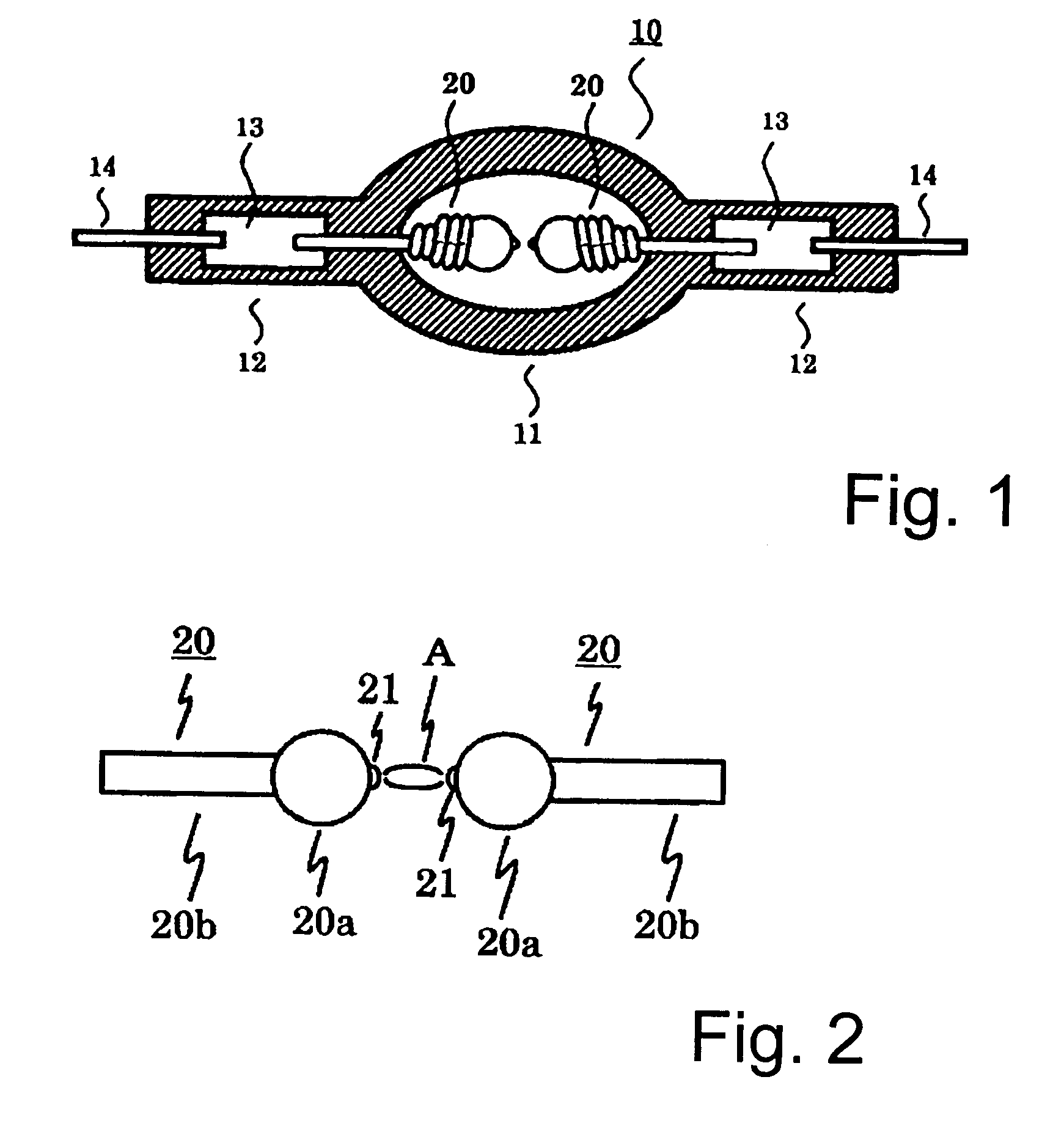
[0040]FIG. 1 schematically shows a high pressure discharge lamp 10 of the invention that has an essentially spherical light emitting part 11 which is formed from a discharge vessel of silica glass. In this light emitting part 11, there is a pair of opposed electrodes 20 that are spaced from each other at a distance of at most 2 mm. Hermetically sealed portions 12 are formed on opposite ends of the light emitting part 11 into which a molybdenum conductive metal foil 13 is hermetically installed by a shrink seal. The support rod of the electrode 20 is connected to one end of each of the metal foil 13. An outer lead 14 is connected to the other end of the respective metal foil 13. Current is supplied by a feed device which is located outside the lamp.

[0041]The light emitting part 11 is filled with mercury, rare gas and halogen gas. The mercury is used to obtain the required wavelength of visible radiation, for example, to obtain radiant light with wavelengths of 360 nm to 780 nm, in an...


PUM


Abstract

To positionally stabilize the arc spot and to prevent the formation of so-called flicker, a super-high pressure discharge lamp which is filled with greater than or equal to 0.20 mg / mm3 of mercury has a feed device which supplies an alternating current with a steady-state operating frequency of from 60 Hz to 1000 Hz and a low frequency of from 5 Hz to 50 Hz. The feed device inserts the alternating current with the low frequency into the alternating current with the steady-state operating frequency with a time interval which has a length equal to at least one half period and at most to five periods, and the time interval being in the range of from 0.1 sec to 120 sec.

Description

BACKGROUND OF THE INVENTION[0001]1. Field of the Invention[0002]The invention relates to a device for operation of a high pressure discharge lamp. The invention relates especially to an operation device which comprises:[0003]a superhigh pressure discharge lamp which is filled with at least 0.2 mg / mm3 of mercury and in which a pressure of at least 200 atm is achieved during operation; and[0004]a feed device for the latter.[0005]2. Description of Related Art[0006]Projector devices are generally of a type using a liquid crystal cell or using a digital light processor (DLP).[0007]The type of projector device using a liquid crystal cell includes a single sheet type and a three-sheet type. In each type, the following takes place:[0008]The radiant light from the light source is separated into three colors (R(ed)G(reen)B(lue)).[0009]The light which corresponds to the video information is transmitted and regulated by a liquid crystal cell;[0010]Afterwards, the three colors which have been tr...

Claims


Application Information

Patent Timeline
Patent Type & Authority Patents(United States)
IPC IPC(8): H05B37/00H01J61/20H01J61/82H01J61/86H05B41/292
CPCH01J61/20H01J61/86H05B41/2928H01J61/827H01J61/073Y02B20/208Y02B20/00
Inventor SUZUKI, YOSHIKAZUSUGAYA, KATUMIARIMOTO, TOMOYOSHI
Owner USHIO DENKI KK
Why Eureka
Try Eureka