Programmable bandwidth during start-up for phase-lock loop

a phase-lock loop and start-up technology, applied in the direction of pulse automatic control, counting chain asynchronous pulse counter, electrical apparatus, etc., can solve the problem of slave-pwms having a tendency to overcorrect, undesirable artifacts appearing in video displays, and unsatisfactory “beat” frequency

Inactive Publication Date: 2006-04-04
INTERSIL INC
View PDF6 Cites 9 Cited by
  • Summary
  • Abstract
  • Description
  • Claims
  • Application Information

AI Technical Summary

Benefits of technology

[0007]One embodiment is a phase lock loop PLL which includes an oscillator having an oscillator signal whose frequency is related to a received error correction signal and phase frequency detector receiving and comparing the oscillator signal and a reference signal from a master circuit and generating the error correction signal based on the phase difference of the oscillator signal and the reference signal. A filter, including a capacitor, connects the error correction signal from the phase-frequency detector to the oscillator. A rate selector monitors a charge on the capacitor and controls the rate of error connection signals as a function of the charge on the capacitor.

Problems solved by technology

If, however, these frequencies are different, undesirable “beat” frequencies can result.
Unfortunately, the beat frequency can cause undesirable artifacts to appear in a video display.
The slave-PWMs have a tendency to overcorrect if there are disturbances on the input signal.
However, in PWM master / slave applications, there are missed pulses if the load current is stepped.

Method used


Image

  • Programmable bandwidth during start-up for phase-lock loop
  • Programmable bandwidth during start-up for phase-lock loop
  • Programmable bandwidth during start-up for phase-lock loop

Examples


Embodiment Construction

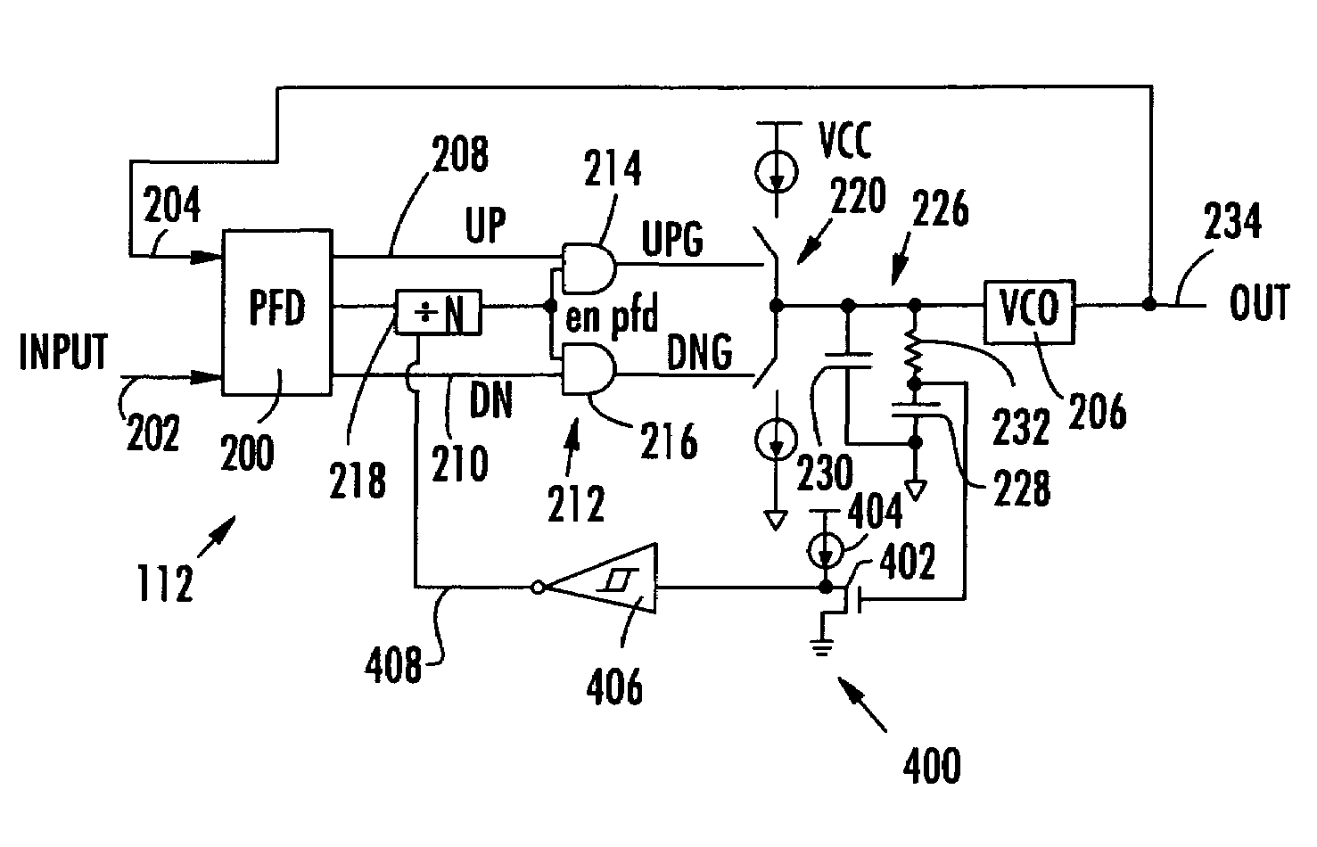
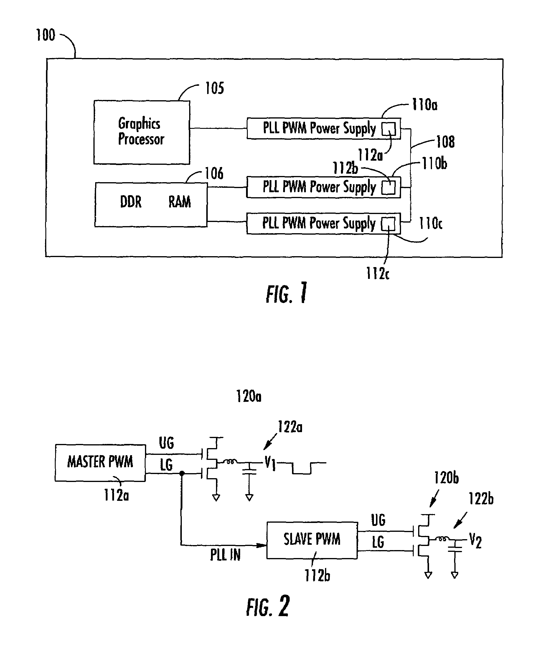
[0025]The PLLs of the present disclosure may be used in the graphic card 100 of FIG. 1, the slave PWM controller 112b of FIG. 2, the WAN transmitter / receiver of FIG. 14 or the computer of FIG. 15. They may also be used in other devices requiring a PLL. The embodiments of FIGS. 4 and 5 are PLLs with a variable rate of transmission of the correction signal.

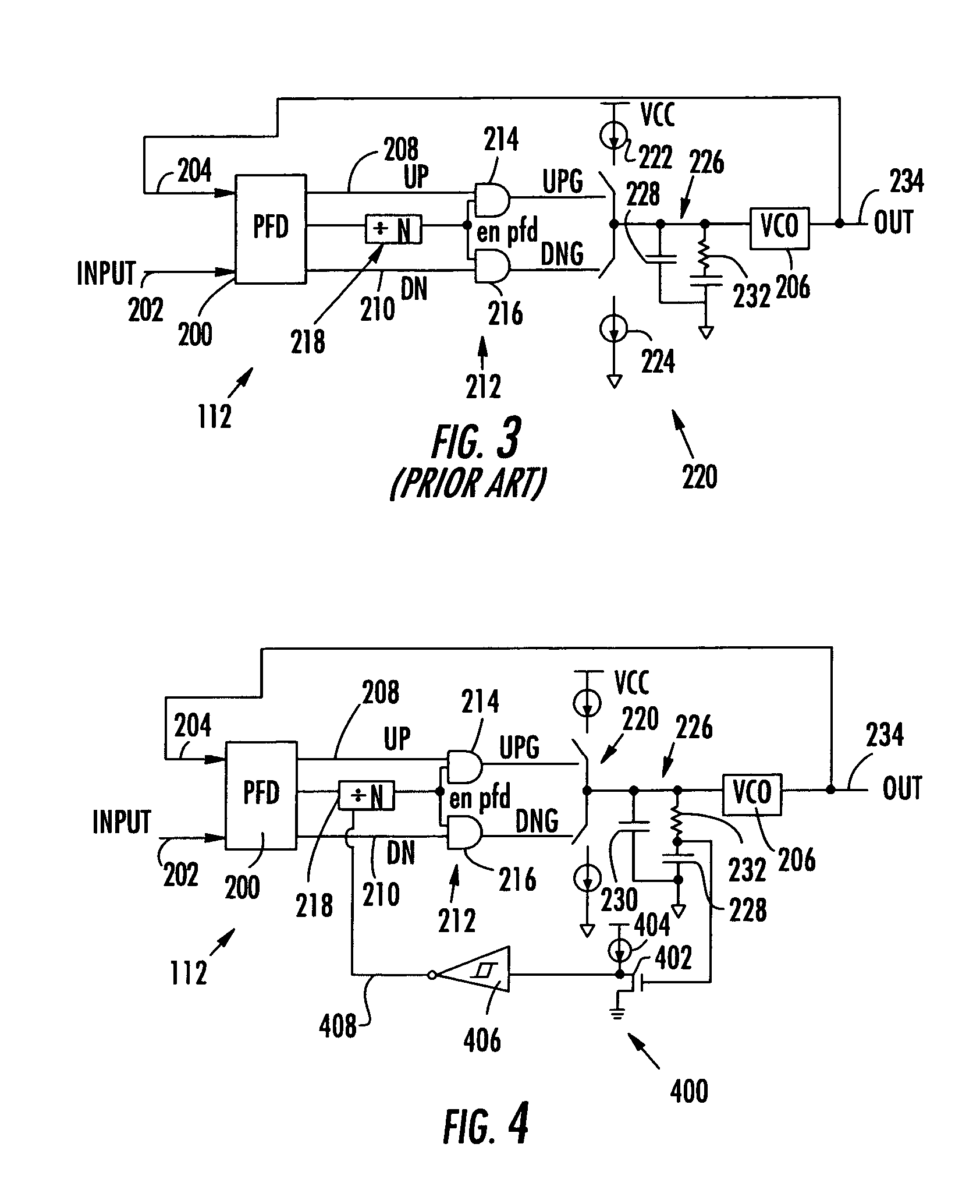
[0026]Those elements of the PLL which are common to that shown of FIG. 3 will have the same reference numbers and function the same way as those elements in FIG. 3. The operation of the PLL including the phase frequency detector (PFD) 200, the counter 218, the logic transmission circuit 212, the charge pump 220, the filter 226 and the VCO 206 are well known and will not be described in detail. Reference will be made to the aforementioned applications, as well as other prior art devices.

[0027]As previously described with respect to FIG. 3, the frequency of the correction pulses UPG and DNG are defined by the period in which the outpu...


PUM


Abstract

A phase lock loop PLL which includes an oscillator having an oscillator signal whose frequency is related to a received error correction signal and phase frequency detector receiving and comparing the oscillator signal and a reference signal from a master circuit and generating the error correction signal based on the phase difference of the oscillator signal and the reference signal. A filter, including a capacitor, connects the error correction signal from the phase-frequency detector to the oscillator. A rate selector monitors a charge on the capacitor and controls the rate of error connection signals as a function of the charge on the capacitor.

Description

CROSS-REFERENCE[0001]This application claims the benefit of U.S. Provisional Application No. 60 / 536,304, filed Jan. 14, 2004; is related to U.S. application Ser. No. 10 / 264,360 entitled PHASE-LOCK LOOP HAVING PROGRAMMABLE BANDWIDTH and U.S. application Ser. No. 10 / 264,359 entitled PWM CONTROLLER WITH INTEGRATED PLL, both of which were filed on Oct. 4, 2002; and all of which are hereby incorporated by reference.BACKGROUND OF THE INVENTION[0002]A graphics board is a printed-circuit board that typically includes at least one graphics processor and other electronic components that process and display graphics or other video data in a computer system. FIG. 1 is a block diagram of a graphics board 100 that includes a graphics processor 105, as discussed in the aforementioned U.S. applications. Typically, one of the electronic components connected to the graphics processor 105 is a double-data-rate random-access memory (DDS RAM) chip 106. Both the graphics processor 105 and the DDR RAM 106...

Claims


Application Information

Patent Timeline
Patent Type & Authority Patents(United States)
IPC IPC(8): H03K5/13H03K23/58H03L7/00H03L7/089H03L7/107
CPCH03K23/58H03L7/107H03L7/0891
Inventor CHEN, SHYNG DUAN
Owner INTERSIL INC
Why Eureka
Try Eureka