
Communication apparatus and e-mail communication method

Active Publication Date: 2006-04-04
MURATA MASCH LTD
View PDF26 Cites 16 Cited by
  • Summary
  • Abstract
  • Description
  • Claims
  • Application Information

AI Technical Summary

Benefits of technology

[0011]An object of the present invention is to provide a communication apparatus that can overcome the above-described problems. Specifically, a primary object of the present invention is to correctly determine who is a true data transmitter (client or communication apparatus itself) when receiving reception acknowledgement from a recipient or a computer on a network in response to an e-mail, and send the reception acknowledgement to the true transmitter.

Problems solved by technology

If the e-mail is not delivered to the recipient, a server where malfunctioning occurs issues a failure notification.
On the other hand, however, when the facsimile server transfers the data from the client, the acknowledgement is not returned to the correct data origin, i.e., client, but the relay station, i.e., facsimile server, since the facsimile server cannot identity the client.

Method used


Image

  • Communication apparatus and e-mail communication method
  • Communication apparatus and e-mail communication method
  • Communication apparatus and e-mail communication method

Examples


Embodiment Construction

[0035]An embodiment of the present invention will now be described with reference to the accompanying drawings.

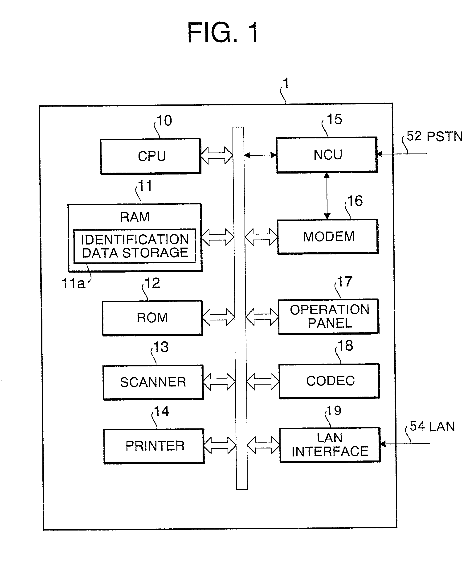
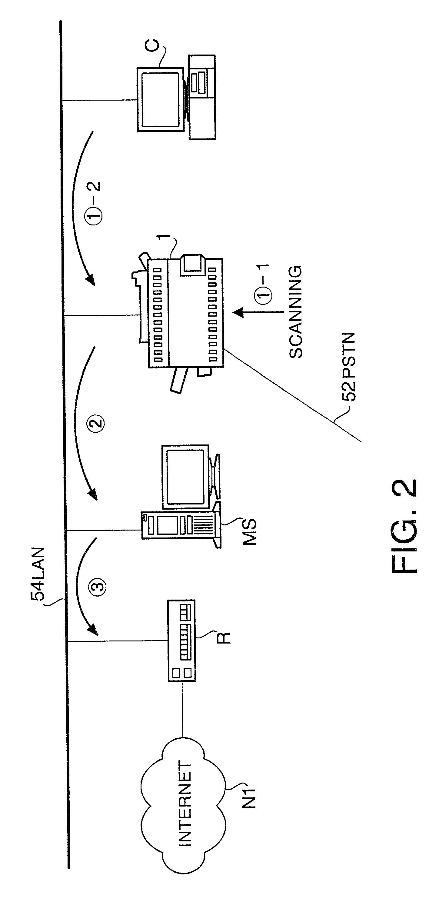
[0036]Referring to FIG. 1, illustrated is a block diagram of a facsimile server 1, which is a communication apparatus of the invention. FIG. 2 schematically illustrates a communication network system incorporating the facsimile server 1.

[0037]The facsimile server 1 is connected to a telephone line (PSTN) 52 and LAN 54. To LAN 54, connected are a router R for connection to the internet N1, a mail server MS, and one or more clients C (only one client is illustrated) as shown in FIG. 2. Clients are personal computers.

[0038]As the facsimile server 1 receives data from the client C as indicated by the arrow {circle around (1)}-2, it transfers the data to a remote facsimile machine over PSTN 52 based on a recipient designated by the client C (designation is made by a facsimile number), or transfers the data in the form of e-mail to the mail server MS as indicated by the arrow {ci...


PUM


Abstract

A facsimile server connected to a mail server and a client over a network, and capable of sending and receiving an e-mail via the mail server. Certain data in a header of an e-mail to be sent to a recipient is used as identification data indicative of an origin of the e-mail. A controller identifies the origin of the e-mail based on the identification data upon receiving reception acknowledgement from the recipient. The facsimile server sends the reception acknowledgement to the client if it determines that the e-mail origin is the client. On the other hand, the facsimile server causes a printer to print the reception acknowledgement if it determines that the e-mail is originated from the facsimile server itself.

Description

CROSS REFERENCES TO RELATED APPLICATIONS[0001]This application claims priority of Japanese Patent Application No. 11-370977 filed in JPO on Dec. 27, 1999 under 35 USC 119, the entire disclosure of which is incorporated herein by reference.BACKGROUND OF THE INVENTION[0002]1. Field of the Invention[0003]The present invention relates to communication apparatus connecting at least a mail server and clients over a communication network and performing e-mail communication via the mail server, and e-mail communication method suitable for such apparatus.[0004]2. Description of the Related Art[0005]Recently, prevailing of communication networks such as internet is remarkable. Even personal computers in houses use WWW (World Wide Web), e-mail, network news, etc. very frequently.[0006]In offices, a communication network such as LAN connects a router for connection to the internet, a mail server, a facsimile server and clients, thereby establishing a communication network system. When the facsi...

Claims


Application Information

Patent Timeline
IPC IPC(8): H04M11/00H04M3/00H04N1/00G06F13/00H04L12/58H04N1/32
CPCH04L51/30H04N1/00209H04L51/28H04N1/32122H04N2201/3218H04N2201/3271H04N2201/0086H04L51/48H04L51/23
Inventor EGUCHI, MASASHI
Owner MURATA MASCH LTD
Learn More