Transmission circuit

a technology of transmission circuit and transmission circuit, which is applied in the field of transmission circuit, can solve the problems of deterioration of adjacent channel leakage power characteristic and inability to keep the power of the control channel data dpcch at the antenna end constant,

Inactive Publication Date: 2006-04-04
LENOVO INNOVATIONS LTD HONG KONG
View PDF7 Cites 29 Cited by
  • Summary
  • Abstract
  • Description
  • Claims
  • Application Information

AI Technical Summary

Benefits of technology

[0014]The present invention has been made in consideration of the above problems in the prior art, and has as its obje...

Problems solved by technology

As the output power decreases, the S/N ratio decreases, resulting in a deterioration in adjacent channel leakage power characteristic.
In the conventional transmission circuit described above, h...

Method used


Image

  • Transmission circuit
  • Transmission circuit
  • Transmission circuit

Examples


first embodiment

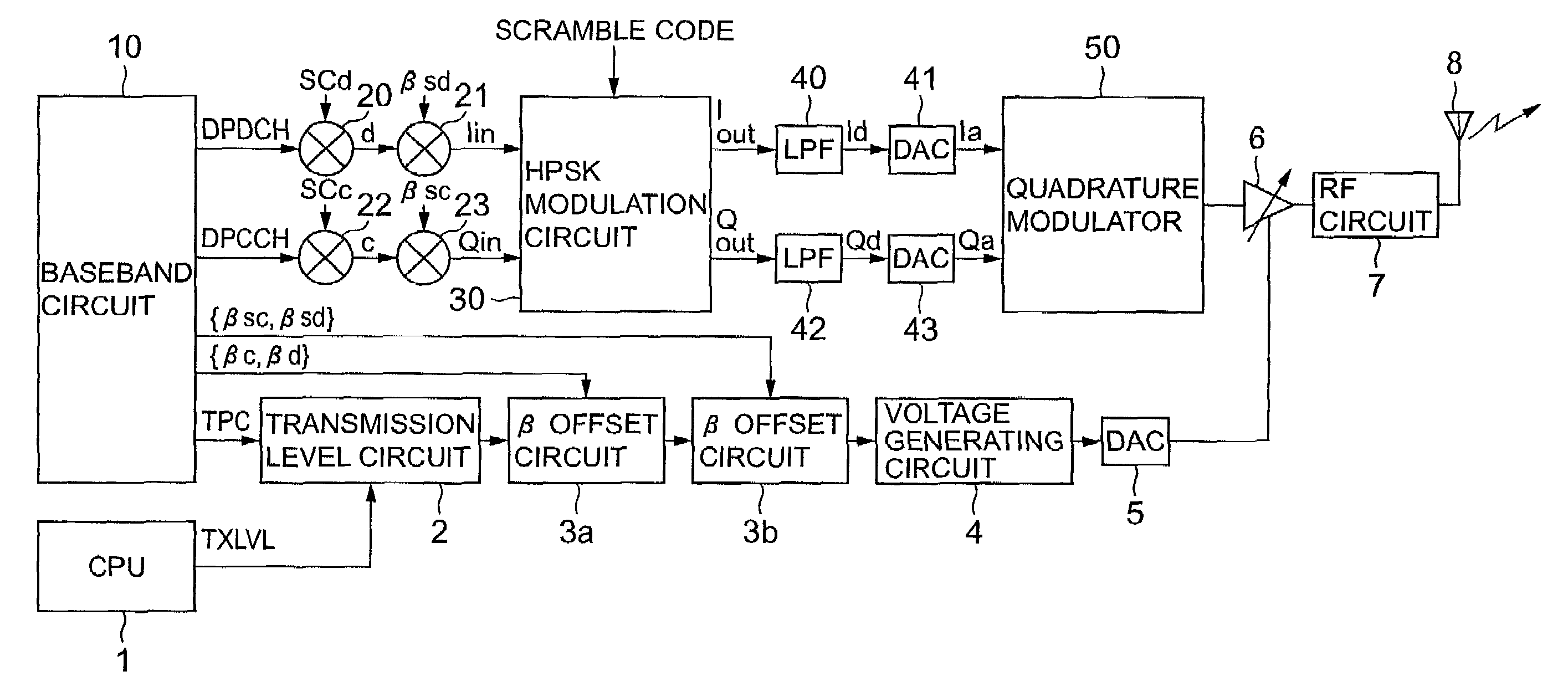
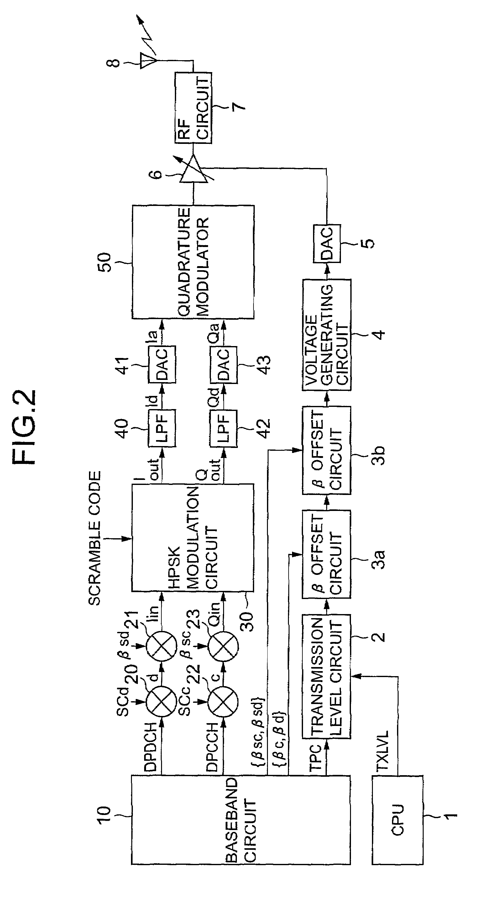
[0052]FIG. 2 is a block diagram showing a transmission circuit according to the present invention.

[0053]As shown in FIG. 1, the first embodiment is comprised of a baseband circuit 10 for generating and outputting two types of transmission data, namely data channel data DPDCH (Dedicated Physical Data Channel) serving as the first channel data and control channel data DPCCH (Dedicated Physical Control Channel) serving as the second channel data and also outputting gain factors βc, βd, βsc, and βsd serving as values for independently weighting I (Inphase) and Q (Quadrature) amplitudes in HPSK modulation and a TPC (Total Power Control) bit for controlling the transmission power of a terminal, a multiplier 20 serving as a spreading means for spreading the data channel data DPDCH output from the baseband circuit 10 by multiplying the data channel data DPDCH by a spreading code SCd, and outputting the resultant data as spread data d, a multiplier 22 serving as a spreading means for spreadi...

second embodiment

[0100]FIG. 7 is a block diagram showing a transmission circuit according to the present invention.

[0101]As shown in FIG. 7, the second embodiment is configured to input a plurality of data channel data DPDCH1 and DPDCH2 and differs from the embodiment shown in FIG. 1 in that it additionally has a multiplier 24 for spreading the data channel DPDCH2 output from a baseband circuit 11 by multiplying the data channel data DPDCH2 by a spreading code SCd2, and outputting the resultant data as spread data d2, a multiplier 25 for outputting amplitude data Iin2 by multiplying the spread data d2 output from the multiplier 24 by a gain factor βsd, and a synthesizing circuit 26 for synthesizing amplitude data Iin1 and the amplitude data Iin2 respectively output from a multiplier 21 and the multiplier 25 and outputting the resultant data to an HPSK modulation circuit 30.

[0102]In the transmission circuit having the above arrangement, the data channel data DPDCH1 and DPDCH2 output from the baseband...


PUM


Abstract

A transmission circuit includes a baseband circuit, spreading section, multiplier, digital modulator, quadrature modulator, and antenna. The baseband circuit generates and outputs at least one transmission data constituted by first and second channel data. The spreading section spreads the transmission data with a spreading code that differs for each transmission channel. The multiplier respectively weights the amplitudes of the first and second channel data by using a combination of two gain factors determined by a transmission data rate. The digital modulator digitally modulates the first and second channel data whose amplitudes are weighted by the multiplier. The quadrature modulator quadrature-modulates the digitally modulated first and second channel data and outputs the data as a transmission signal. The antenna emits the transmission signal output from the quadrature modulator as a radio wave. The multiplier weights the amplitudes of the first and second channel data by using gain factors that keep power of the transmission signal output from the quadrature modulator constant regardless of the transmission data rate without changing the ratio of a combination of gain factors determined by the transmission data rate.

Description

BACKGROUND OF THE INVENTION[0001]1. Field of the Invention[0002]The present invention relates to a transmission circuit provided in a communication terminal and, more particularly, to a transmission circuit using the HPSK (Hybrid Phase Shift Keying) modulation scheme.[0003]2. Description of the Prior Art[0004]In the HPSK modulation scheme described in 3G TS 25.213 of 3GPP (3rd Generation Partnership Project) which is a standardization project for W-CDMA (Wide band Code Division Multiple Access) specifications, transmission data is spread by a spreading code first, and then the spread transmission data is multiplied by a gain factor to perform amplitude weighting in HPSK modulation so as to obtain amplitude data. Thereafter, this amplitude data is HPSK-modulated.[0005]FIG. 1 is a block diagram showing an example of the arrangement of a conventional transmission circuit using the HPSK modulation scheme.[0006]As shown in FIG. 1, this conventional circuit is comprised of a baseband circ...

Claims


Application Information

Patent Timeline
IPC IPC(8): H04B1/69H04B1/707H04B1/713H04L27/20H04B1/04H04J13/00
CPCH04B1/707H04J13/00H04J13/0077H04B2201/70703
Inventor KURIHARA, KAZUHIRO
Owner LENOVO INNOVATIONS LTD HONG KONG
Why Eureka
Try Eureka