
Network system, control method, control apparatus, and multiprocessor

Inactive Publication Date: 2006-04-04
ORMON CORPORATION
View PDF4 Cites 26 Cited by
  • Summary
  • Abstract
  • Description
  • Claims
  • Application Information

AI Technical Summary

Benefits of technology

[0021]Moreover, the control apparatus may be provided with updating stop command operation means, and means for prohibiting the execution of said updating process when a stop command is issued from the updating stop command operation means. The updating stop command operation means correspond to the “name solving lock switch” in the embodiments. This invention is achieved by the embodiment that executes the flowchart shown in FIG. 56. In the case where it is understood that there is no need for the updating process, by operating such updating stop command means to output a stop command, it is possible to proceed to the actual program execution without carrying out the process which judges whether or not the updating process is needed. Accordingly, a quicker setup can be carried out.
[0042]When constructed in this way, for example, by writing the content corrected by the online edit into the indirect reference table during a nonuse state, and then, for example, by switching the indirect reference table updated by the newly written content to a use state at a prescribed timing when a reference to the indirect reference table is not being carried out or the like, it becomes possible to rewrite the indirect reference table even when the user program and the like are operating, and this makes it possible to shorten the stopping time as much as possible.

Problems solved by technology

However, the prior art methods described above have the problems described below.
Namely, in the former method which uses a user program, it is necessary to bury communication logic inside the ladder program for operating the control apparatus (PLC), the development of the user program becomes complex, and maintenance is difficult.
Further, in the case of the latter data link method, it is difficult to establish the allocation of memory area at the time data is linked.
Accordingly, after a memory area allocation has been temporarily established, if there is a change in this memory area allocation, the user program thereof needs to be rewritten, and this creates complications.
Moreover, in the case where a new control apparatus is added to the network, the reallocation of the memory area and the accompanying changes to the user program must be made up to the existing user programs provided in control apparatuses already connected to the network, and there is the problem that the system must be shut down.

Method used


Image

  • Network system, control method, control apparatus, and multiprocessor
  • Network system, control method, control apparatus, and multiprocessor
  • Network system, control method, control apparatus, and multiprocessor

Examples


Embodiment Construction

[0103]The present invention will now be described in greater detail with reference to the appended drawings.

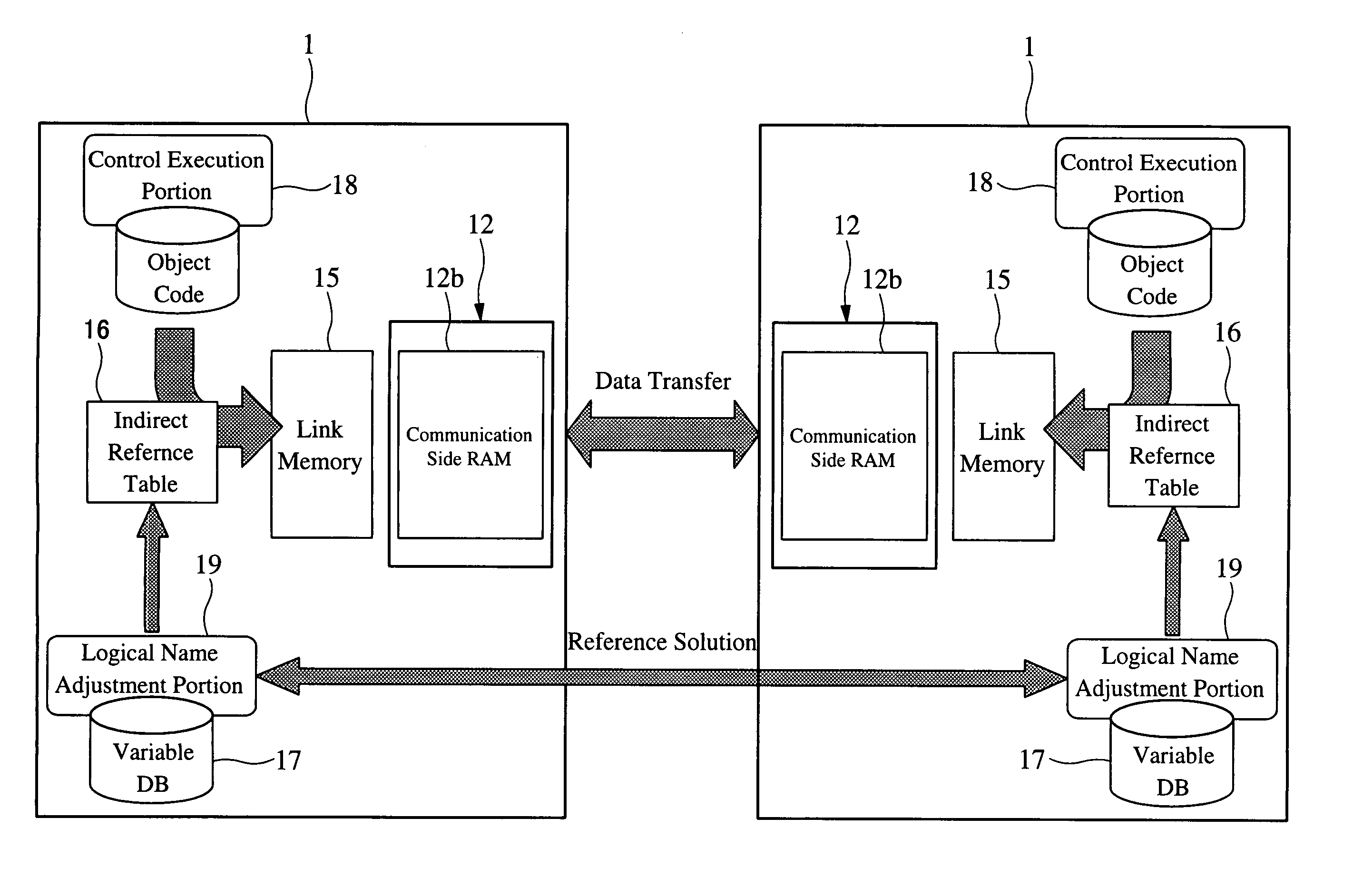
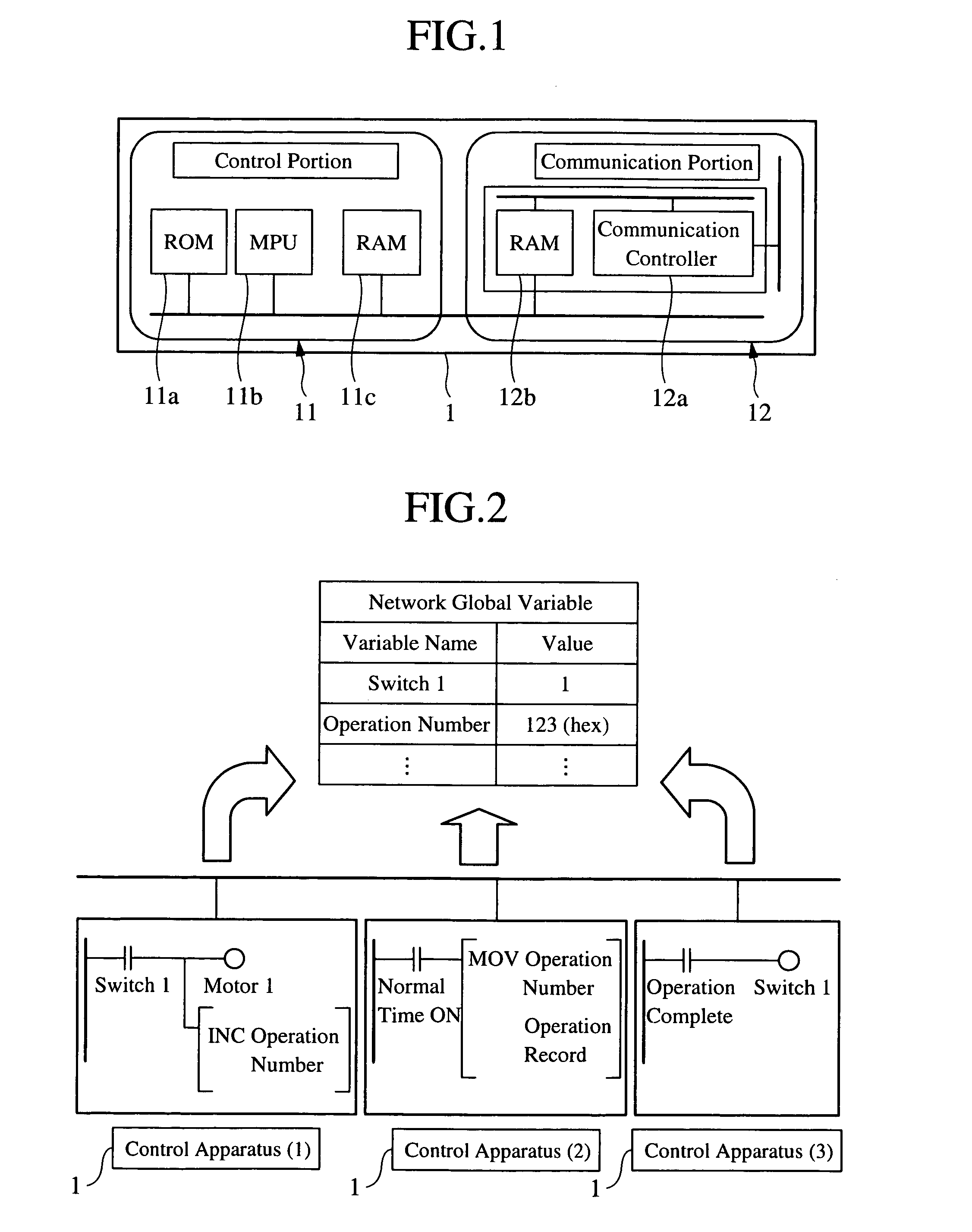
[0104]FIG. 1 shows a preferred embodiment of a control apparatus according to the present invention. As shown in this drawing, the control apparatus is equipped with a control portion 11 and a communication portion 12. The control portion 11 executes a ladder program, and carries out essential control of the control apparatus, namely, a PLC 1. The communication portion 12 is connected to a network, and possesses a function for communicating with other control apparatuses. Specifically, the communication portion 12 includes a communication controller 12a which is connected to the network for carrying out transmission and reception of data (common data exchange when stated by the relationship with the present invention) by a prescribed communication protocol, and a RAM 12b which temporarily stores data at the time protocol changes are made when communication control is carried o...


PUM


Abstract

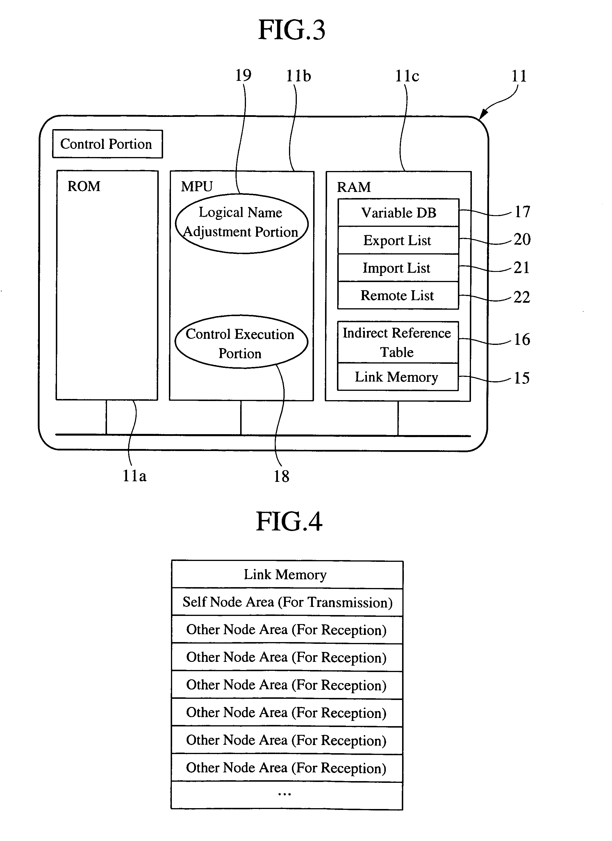
A logical name of shared data is defined. A network system comprises a communication portion for exchanges of data with other control apparatuses; a link memory (15) for storing data shared through the network; an indirect reference table (16) for storing logical names and the pointers used to access data stored in the link memory; and a database (17) of variables in which logical names are associated with memory addresses in the indirect reference table storing the pointers of the logical names. A control execution portion (18) accesses the link memory through the indirect reference table based on a logical name so that there is no need to know the specific memory location. Specifically, the user program contains logical names and no addresses (pointers) storing data.

Description

TECHNICAL FIELD[0001]The present invention is related to a network system, a control method, a control apparatus, and a multiprocessor system. More specifically, the present invention is related to improvements of processes of sharing data in a system (e.g., a distribution control system or the like) for planning the sharing of data between a plurality of nodes, control apparatuses and processors.PRIOR ART TECHNOLOGY[0002]There are situations where control apparatuses of PLCs or the like of a plurality of platforms are connected to a network, and these plurality of apparatuses execute cooperation / synchronization controls and the like while sharing data. In such case, in order for each control apparatus to share data, the respective I / Os thereof are physically connected, or a user program for sharing data is used.[0003]Further, as another method of having each control apparatus share data, there is also the so-called data link method. This data link method is a method in which data i...

Claims


Application Information

Patent Timeline
IPC IPC(8): G06F15/16G06F12/00G05B19/05H04L29/06H04L29/08
CPCG05B19/052H04L67/1097G05B2219/15118G05B2219/13125
Inventor HITOMI, SHIGERUDEKI, JINTAROSASAMORI, TOSHIAKI
Owner ORMON CORPORATION
Learn More