Case knife with multiple position blade guards

Inactive Publication Date: 2006-04-11
SPECMASTER
View PDF11 Cites 39 Cited by
  • Summary
  • Abstract
  • Description
  • Claims
  • Application Information

AI Technical Summary

Benefits of technology

[0006]Accordingly, it is an object of the subject inventive case knife to provide a case knife construction that provides separately operable guards, each one on each side of a replaceable blade to thus flank the blade. The blade is held in a fixed position within the handle shell and positioned between each of the two

Problems solved by technology

A problem with prior case knives is that it is very difficult to control the depth to which the blade, (usually a replaceable and disposable steel blade such as a single-edge razor blade), penetrates through the corrugated cardboard panel or edge of a case.
Inadequate penetration can result in inefficiencies.
For example, the lid or panel of the corrugated cardboard case will not fully separate from the base.
Perhaps more importantly a case knife blade, if it penetrates too deeply into the corrugated cardboard panel, can damage the packing case contents.
If the contents are foodstuffs, such too deep penetrations can result in spoilage or consumer rejection of the products, as for example when the case knife blade has opened the individual packages of food, such as breakfast cereals and the like.
Another problem

Method used


Image

  • Case knife with multiple position blade guards
  • Case knife with multiple position blade guards
  • Case knife with multiple position blade guards

Examples


Embodiment Construction

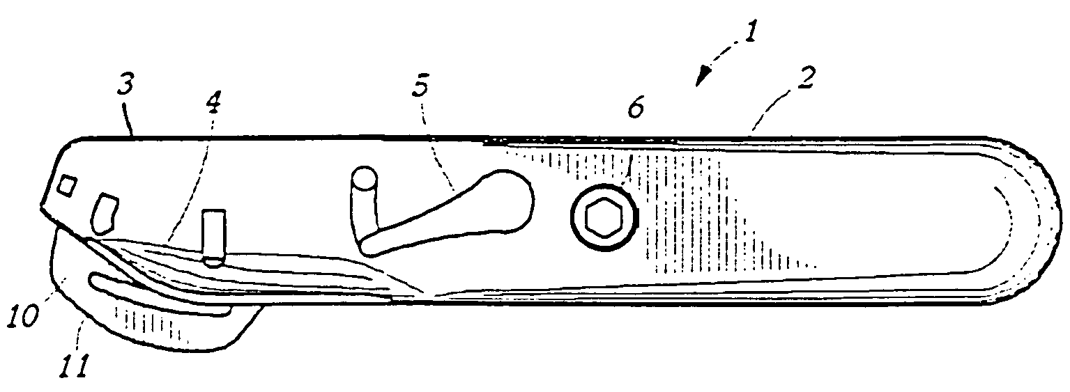
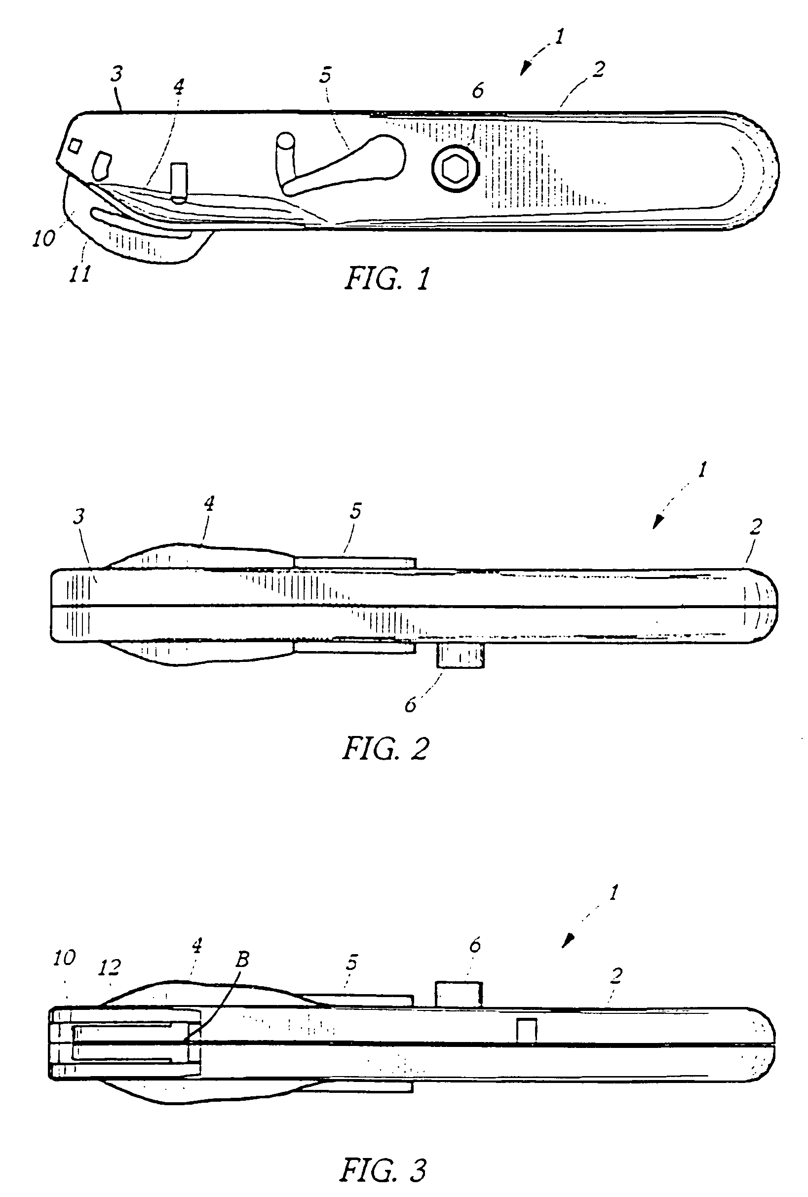
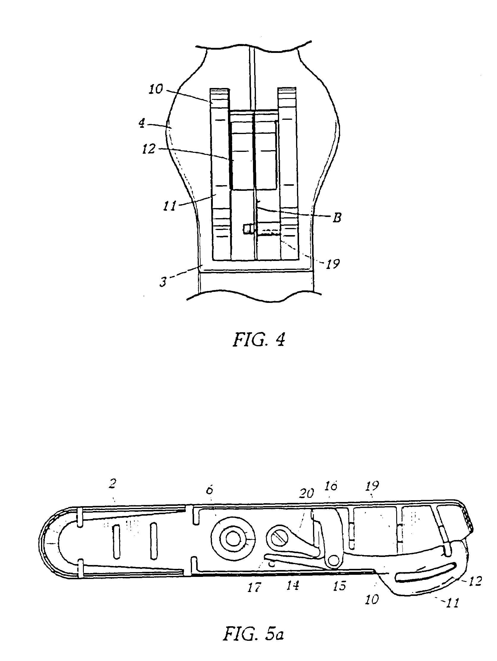
[0027]The case knife 1 has a generally elongated, prismatic shape, typical of the conventional case knives used in the grocery or supermarket industry. There is a grip portion 2 towards one end and a blade-containing portion 3 at the opposite end. Along one lower edge of each side of the blade containing end or portion 3 protrude a pair of thumb rests 4, consisting of a pair of protruding flanges, generally symmetrically identical. These are integrally molded to protrude on each of the two shells halves making up the case knife shell. On each case knife shell half there is a generally elongated, thumb-operated button or lever 5, which pivots around its axle 14 and has at least two operative positions, as will be detailed.

[0028]A conventional knurled bolt 6 engages embedded nut 7 to hold the two shell halves together during use and to clamp and hold the blade B between the two shell halves. Each shell half includes protrusions 19 which also engage and hold the blade firmly and in the...


PUM


Abstract

A case knife (1, 101), generally consists of a pair of substantially symmetrical handle shells (13, 112). A single edge razor blade B is removably supported in one end of the handle formed by these handle shells. Each handle shell includes two moving parts—a guard (10, 110) and a thumb or finger operable button (5, 105). Each such guard, when paired with a substantially identical guard of the other handle half shell, flanks the otherwise protruding sharp edge of the razor blade. Each guard can move independently to expose a protruding corner of the razor blade. The operable button is mounted on an axle or lug (14, 103) that passes from the inside of a handle shell, through to its outside surface. This axle is in turn fixed to a cam follower (20, 120) mounted on the inside of each shell.

Description

CROSS REFERENCE TO RELATED APPLICATIONS[0001]This application is related to Provisional Patent Application Ser. No. 60 / 332,656 filed Nov. 21, 2001, and claims benefit of this provisional application's filing date. This application is also related to Design Patent Application Serial No. 29 / 150,554, which was also filed on Nov. 21, 2001.BACKGROUND OF THE INVENTION[0002]This invention deals generally with so-called case knives, that is knives specifically designed to cut open corrugated cardboard packing cases or cartons. A problem with prior case knives is that it is very difficult to control the depth to which the blade, (usually a replaceable and disposable steel blade such as a single-edge razor blade), penetrates through the corrugated cardboard panel or edge of a case. Inadequate penetration can result in inefficiencies. For example, the lid or panel of the corrugated cardboard case will not fully separate from the base. Perhaps more importantly a case knife blade, if it penetrat...

Claims


Application Information

Patent Timeline
IPC IPC(8): B26B3/08
CPCB26B5/005B26B29/02B26B27/005B26B5/006
Inventor SHAVER, BILLY J.BUSBY, RANDY R.CARTER, JAMES S.
Owner SPECMASTER
Why Eureka
Try Eureka