Framework connection system

a connection system and framework technology, applied in the direction of rod connection, coupling, instruments, etc., can solve the problems of large display size and complexity, high display cost, and high convention space, and achieve easy interconnection, simple, and increased connectivity options.

Inactive Publication Date: 2006-04-11
SKYLINE DISPLAY LLC
View PDF65 Cites 50 Cited by
  • Summary
  • Abstract
  • Description
  • Claims
  • Application Information

AI Technical Summary

Benefits of technology

[0006]The display of the present invention addresses and solves many of the described problems that innately plague conventional displays. The present invention employs various individual components that are easily interconnectable to provide the end user with a myriad of framework configuration options utilizing large diameter tubing. These components can be selectively connected so that only those components are used that provide the user with the optimal configuration. As such, connectivity options are increased with the selective combination of only those components which are needed to meet the user's needs. In addition, the relatively simplistic design of the components and locking options of the present invention improves ease of assembly, disassembly, and reconfiguration.

Problems solved by technology

To create desired attention-getting appeal, such displays can be massive in size and complexity.
Moreover such convention space is usually extraordinarily expensive as is labor for set up and take down of the displays.
Such constraints often make these displays quite expensive.
While all of these systems have their advantages, the collapsible systems cannot support extensive weight and the exposed truss systems present an industrial look.
Such systems have been used in trade show type displays but have not had the flexibility and reconfigurability desirable in this type of product line.
Currently, such large framework systems are cumbersome and are often designed with one particular configuration in mind.
An inability to selectively design and setup such steel tubular framework systems is problematic.

Method used


Image

  • Framework connection system
  • Framework connection system
  • Framework connection system

Examples


Embodiment Construction

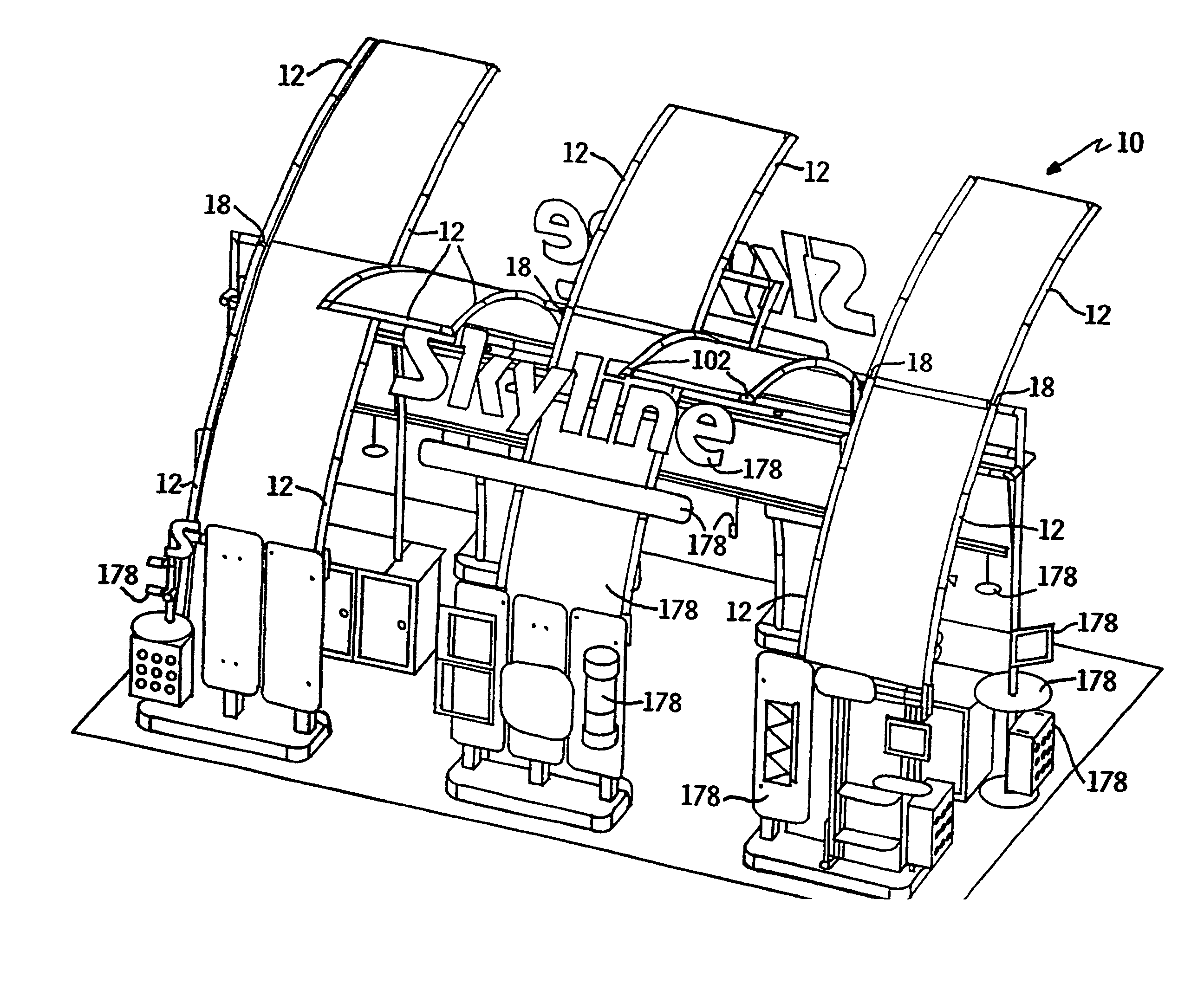
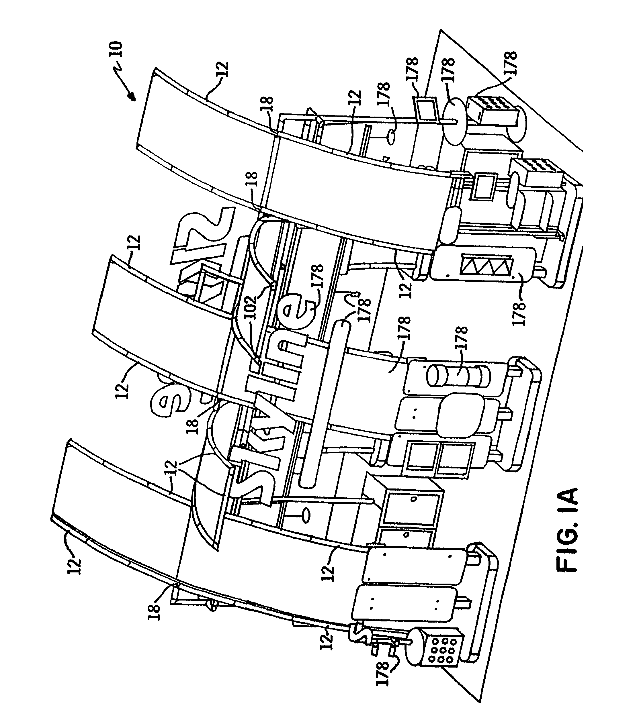
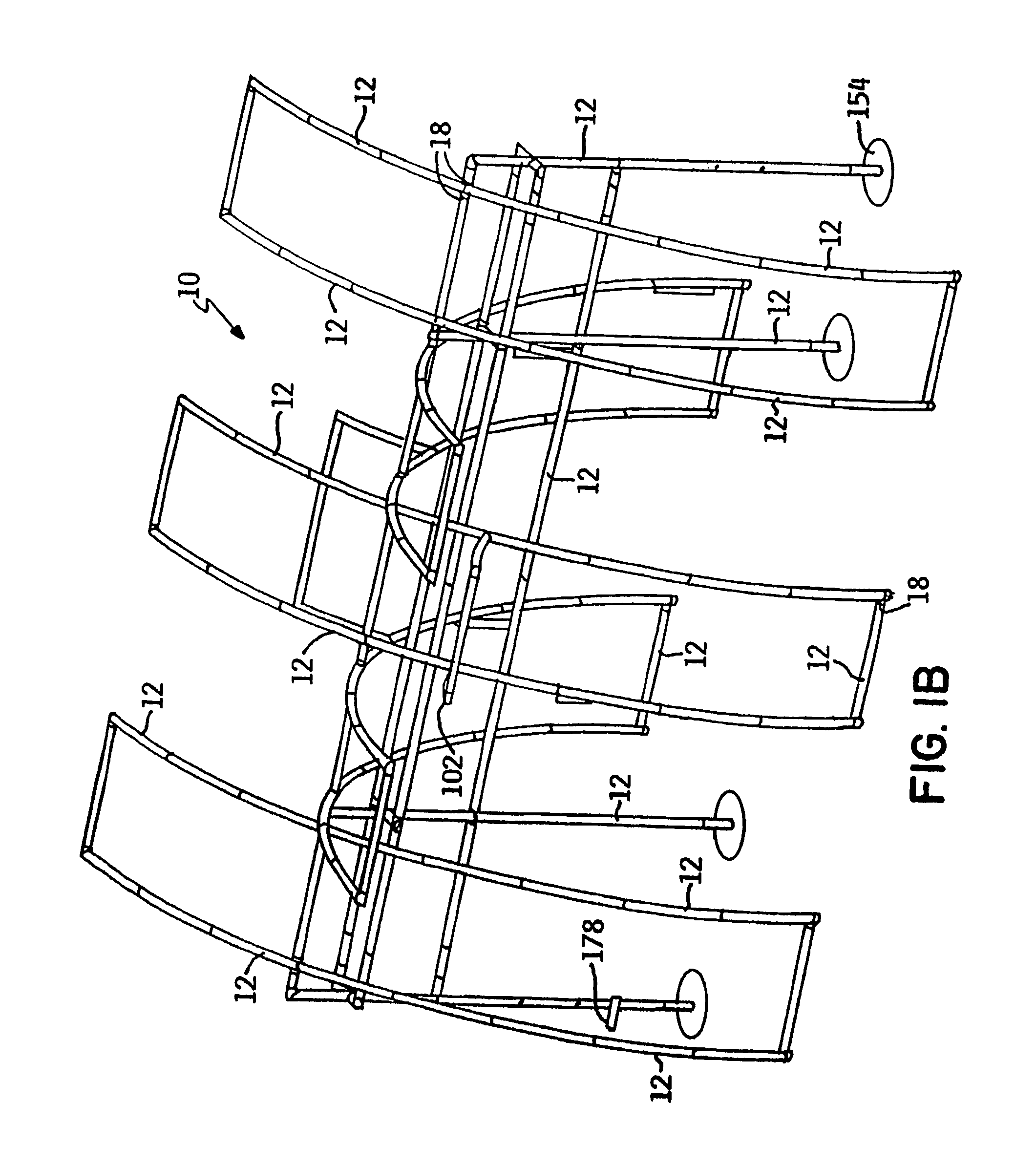
[0058]Referring primarily to FIGS. 1a–21, the framework connection system 10 in accordance with the present invention generally comprises a plurality of frame members 12, a plurality of end flanges 14, a hub plate assembly 16, and a hub assembly 18. Various embodiments of the system 10 components, means of connectivity, and configuration options are described and shown in attached Appendix A, which is hereby incorporated by reference in its entirety. The frame members or segments 12 can be tubular steel tubing members, but in alternative embodiments, other materials and shapes can be employed. Each of the end flanges 14 are insertably attachable to at least one end of the frame member 12 such that the flange 14 is fixed within at least a portion of the tubing member 12. The flanges 14 can be fixed to the end portion of the frame member 12 with a weldment bond to facilitate connectivity with other system 10 components. Other methods and techniques of attachment understood to one skil...


PUM


Abstract

A display framework connection system comprising a plurality of frame members, preferably tubular, a plurality of end flanges, and a hub system. The hub system can comprise a hub plate assembly and/or a hub casting assembly. In addition, at least one clamp assembly, preferably cylindrical, can be included for circumferential attachment to the outer surface of the frame members to provide for selective removable fastening of various attachments and accessories at positions along the length of the frame members. The hub plate assembly and the hug casting assembly can be connected individually to the frame members, or in combination, to enable selective angular configuration of the frame members to construct a frame construction, such as those commonly utilized in display frame systems.

Description

RELATED APPLICATIONS[0001]The present invention claims the benefit of U.S. Provisional Application No. 60 / 390,489 filed Jun. 21, 2002 and entitled “Framework Connection System,” which is hereby incorporated by reference in its entirety.FIELD OF THE INVENTION[0002]The present invention is related generally to displays having support framework and graphical displays for use as exhibits at trade shows and the like. More particularly, the invention relates to such displays that are dissassemblable and that utilize tubular components to selectively vary the frame configuration.BACKGROUND OF THE INVENTION[0003]Exhibits for tradeshows and other marketing venues utilize eye catching and informative graphical portions that are intended to inform and present an image to customers or potential customers. A common use will be at convention or exposition halls where perhaps a single day is allocated for each of setup and removal. To create desired attention-getting appeal, such displays can be m...

Claims


Application Information

Patent Timeline
Patent Type & Authority Patents(United States)
IPC IPC(8): E04H12/00A47B43/00E04B1/58E04CE04H1/12E04H17/00F16B7/18F16B9/02F16B21/16F16D1/00G09F15/00
CPCE04H1/1272F16B9/026G09F15/0068F16B7/185E04B1/5837E04B2001/5868Y10T403/341F16B21/16F16B9/056F16B9/09
Inventor GIMPEL, DIXON S.LINDBLOM, CURTIS H.
Owner SKYLINE DISPLAY LLC
Why Eureka
Try Eureka