Automatically-closing screen door and closing speed adjuster for the same

Inactive Publication Date: 2006-04-11
DONNELLY JOHN D
View PDF5 Cites 15 Cited by
  • Summary
  • Abstract
  • Description
  • Claims
  • Application Information

AI Technical Summary

Benefits of technology

[0012]Invention overcomes the limitations of the prior art by offering a simple manufacture, assembly and operation. It has a low profile relative to the door jamb, has a low cost to manufacture and has little resistance when opening the sliding screen door.
[0016]The door frame can comprise a door jamb and the automatic closure system can further comprise a cover mounted on the door jamb to visually conceal the pulley, the second end of the cable, and the counterweight. The counterweight can have a thin profile so that the counterweight can easily be concealed under the cover. The counterweight can be at least one of a lead plate, a lead rod, a lead member, a lead-filled tube and a stainless steel member. The cover can have an opening to permit the cable to pass through the cover. The cover can have an elongated shape so that the cover can have an appearance similar to and blends in with the door jamb.
[0017]The automatic closure system can further comprise an adjuster to control movement of the counterweight between the counterweight open and counterweight closed positions. The adjuster can comprise a housing and a U-shaped member fastened to the housing, wherein the cable is received within the U-shaped member. The U-shaped member can be selectively moved toward the housing to constrict the cable between the U-shaped member and the housing, thereby restricting movement of the cable through the adjuster, retarding movement of the counterweight, and causing the sliding door to slide more slowly to the door closed position. The U-shaped member can be selectively moved away from the housing to loosen the cable, thereby causing the sliding door to slide at a faster rate to the door closed position. The adjuster can further comprise thumb screws to move the U-shaped member relative to the housing.
[0018]The door frame can comprise a door jamb, the automatic closure system can further comprise a cover mounted on the door jamb to visually conceal the pulley, the second end of the cable, and the counterweight, and the adjuster is mounted to one of the door jamb and the cover. The door frame can comprises a door jamb; the automatic closure system further comprises a cover mounted on the door jamb to visually conceal the pulley, the second end of the cable, the counterweight, and the adjuster; and wherein the adjuster comprises an arm having a first end mounted to the cover and a second end that extends towards the door jamb and abuts the counterweight as it moves between the counterweight open and counterweight closed positions, wherein the second end of the arm imparts a damping force onto the counterweight as it moves between the counterweight open and counterweight closed positions, thereby causing the sliding door to move more slowly between the door open position and the door closed position.
[0019]The adjuster can further comprise a bias adjuster to control the damping force imparted onto the counterweight by the arm. The bias adjuster can comprise a threaded fastener that is mounted through the cover and contacts the arm between the first and second ends of the arm so that movement of the threaded fastener towards the arm increases the amount of damping force exerted by the arm and movement of the threaded fastener away from the arm decreases the amount of damping force exerted by the arm. The arm can be comprised of a resilient material.

Problems solved by technology

However, if the sliding screen door is left in an open position, the sliding screen door does not return to the closed position on its own accord.
This can be a problem if the occupant has young children who frequently forget to close the sliding screen door after entering or leaving the dwelling.
In addition, if the occupant is entering or leaving the dwelling carrying an object or performing an activity that requires both of the occupant's hands (e.g., carrying trays of food), it may also be difficult to manually close the sliding screen door in an acceptable amount of time.
These spring-based automatic closure systems have some problems.
Third, repair of these so-called spring-based automatic closure systems can be difficult and costly.
Fourth, the spring used in the so-called spring-based automatic closure system can lose elasticity over time and require replacement.

Method used


Image

  • Automatically-closing screen door and closing speed adjuster for the same
  • Automatically-closing screen door and closing speed adjuster for the same
  • Automatically-closing screen door and closing speed adjuster for the same

Examples


first embodiment

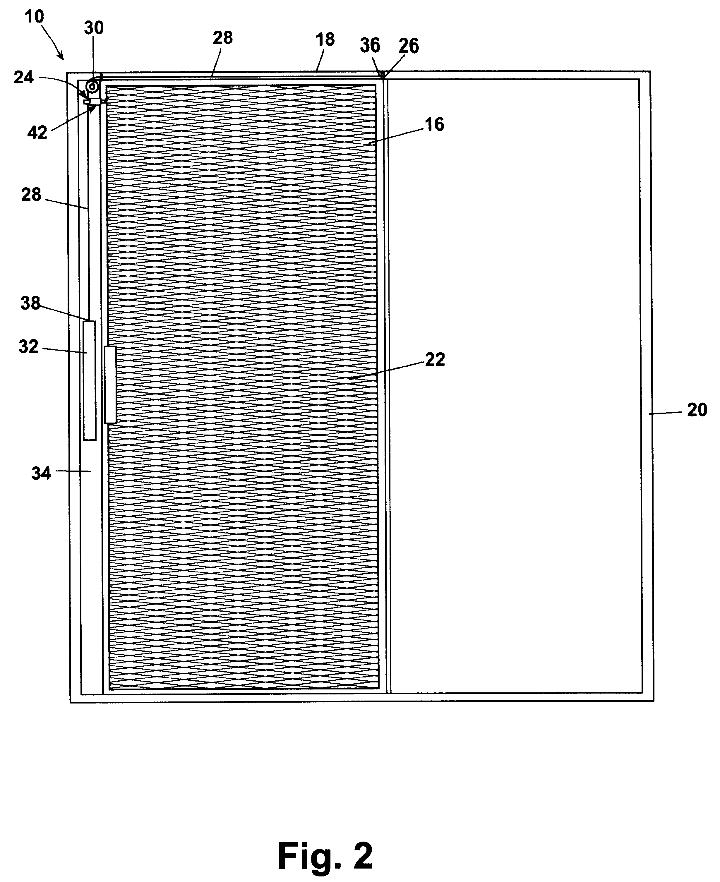
[0035]In accordance with the invention, an automatic closure system 24 is mounted between the sliding glass door frame 18 and the screen door 16. The automatic closure system 24 comprises a bracket 26, a cable 28, a pulley 30, a counterweight 32 and a cover 34.

[0036]The bracket 26 is preferably mounted to an upper portion of the screen door 16. The pulley 30 is preferably mounted to the cover 34 in generally horizontal planar alignment with the bracket 26. A first end 36 of the cable 28 is mounted to the bracket 26 at the upper portion of the screen door 16. A second end 38 of the cable 28 is mounted to the counterweight 32. As can be seen in FIGS. 2 and 3, the cable 28 is fed over the pulley 30 so that the counterweight is hung generally vertically by the second end 38 of the cable 28 and the first end 36 of the cable imparts a closure force on the screen door 16. The cover 34 is mounted over the pulley 30, the second end 38 of the cable 28, and the counterweight 32. Preferably, th...

second embodiment

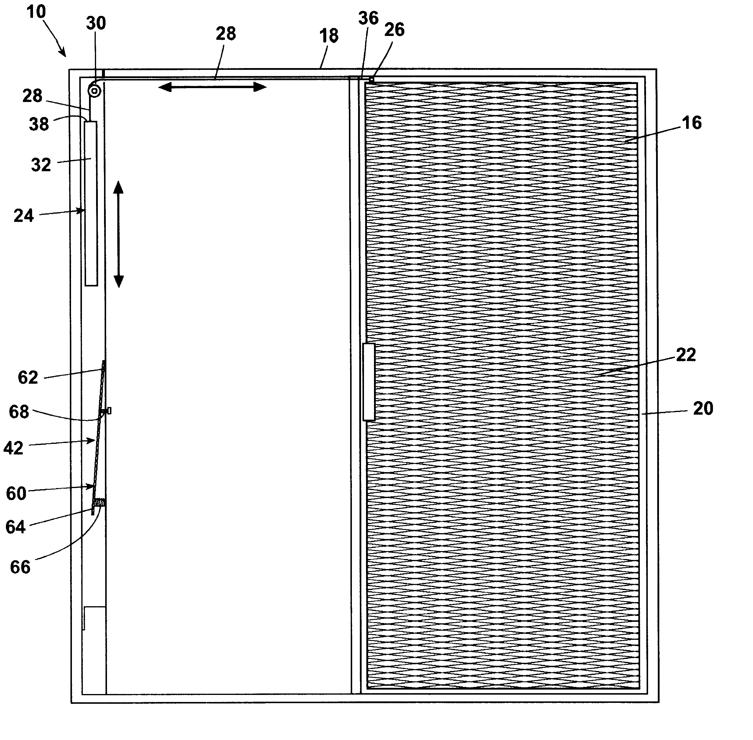
[0050]the automatic closure system 24 also includes a counterweight 32 located within a suitable cover 34, however, in this embodiment, the adjuster 42 for controlling the closing speed of the screen door 16 comprises an arm 60 having a first end 62 mounted to an interior portion of the cover 34 and a second end 64 extending inwardly therefrom in register with an axial path of travel of the counterweight 32 between the open and closed positions of the door.

[0051]Preferably, the arm 60 is mounted so that the second end 64 thereof is positioned to abut the counterweight 32 as it moves toward the closed position of the screen door 16. The second end 64 of the arm 60 can be biased into the counterweight travel path by a spring 66, preferably mounted between the second end 64 of the arm 60 and the cover 34. Preferably, the arm 60 is mounted to the cover 34 at a desirable vertical height so that the counterweight 32 contacts the arm 60 during its travel as the screen door 16 moves between...


PUM


Abstract

An automatically-closing screen door is provided that is typically for enclosure with a conventional sliding glass door used for patio entry in residential and / or commercial dwellings. The automatically-closing screen door preferably has a counterweight that is employed to provide a controllable closing force to the door.

Description

CROSS REFERENCE TO RELATED APPLICATIONS[0001]This application claims the benefit of U.S. Provisional Application Ser. No. 60 / 319,397, filed Jul. 15, 2002, and U.S. Provisional Application Ser. No. 60 / 319,752, filed Dec. 4, 2002, both entitled “Automatically-Closing Screen Door and Closing Speed Adjuster for the Same.”BACKGROUND OF INVENTION[0002]1. Field of the Invention[0003]The invention relates to an automatically-closing screen door, typically for enclosure with a conventional sliding glass door used for patio entry in residential and / or commercial dwellings. More particularly, the invention relates to an automatically-closing screen door in which a counterweight is employed to provide a controllable closing force to the door.[0004]2. Description of the Related Art[0005]Sliding glass door assemblies have become commonplace in both residential and commercial dwellings. A sliding door is mounted on a horizontal track in offset alignment with a fixed door. When an occupant of a dwe...

Claims


Application Information

Patent Timeline
IPC IPC(8): E05F1/02E06B9/52
CPCE05F1/025E06B9/52Y10T16/602E05Y2900/136
Inventor DONNELLY, JOHN D.
Owner DONNELLY JOHN D
Why Eureka
Try Eureka