Mold and method of molding metallic product

a technology of metallic products and molds, which is applied in the direction of casting apparatus, manufacturing tools, melt holding vessels, etc., can solve the problems of difficult repeating heating and cooling, long time required to increase the temperature, and the production of metallic molded products, so as to shorten the cycle time of molding operation, and the fluidity of the molten metal is sufficien

Inactive Publication Date: 2006-04-11
DENSO CORP
View PDF6 Cites 2 Cited by
  • Summary
  • Abstract
  • Description
  • Claims
  • Application Information

AI Technical Summary

Benefits of technology

[0007]The present invention has been made to solve the above-mentioned problems in the prior art, and an object thereof is to provide a mold and a method for molding a metallic product, capable of restricting the transfer of heat from the molten material to the mold during the filling of the molten metal into the mold to ensure the fluidity thereof on one hand, and accelerating the transfer of heat after the molten metal has been filled in the mold on the other hand.
[0008]According to one aspect of the present invention, the fixed mold section of the mold is provided with heating means and the movable mold section is provided with cooling means, both of which means are controlled by temperature control means, respectively, so that the temperature variations in one cycle of the fixed and movable mold sections are individually controllable. Thereby, it is possible to heat the fixed mold section even if the mold is in an open state to shorten the cycle time of the molding operation. Also, it is possible to heat the fixed mold section side to a higher temperature to ensure the sufficient fluidity of the molten metal to be filled.
[0009]According to the inventive mold, the fixed mold section is disposed on the injection side of molten metal to be molded, and ejector pins for releasing a molded metallic product from the movable mold section are provided in the movable mold section. Thereby, while ensuring the sufficient fluidity of the molten metal, the lowering of the temperature of the movable mold section side is enhanced. As a result, the removal of the molded product by the ejector pins is accelerated.
[0010]According to the inventive mold, when the mold is in an open state, the temperature of the fixed mold section rises to a value in a range from 300 to 700° C., and the temperature of the movable mold section is controlled to a value in a range from a solidifying point of the metal to be molded to 0° C. Thereby, it is possible to increase the temperature of the fixed mold section and to reduce that of the movable mold section when the mold is in an open state.
[0011]According to another aspect of the present invention, a method for molding a metallic product is provided which comprises the steps of heating the fixed mold section by the heating means and cooling the movable mold section by the cooling means when the mold is open; closing the mold during the heating of the fixed mold section and the cooling of the movable mold section, heating the fixed mold section by the heating means and cooling the movable mold section by the cooling means even after the mold has been closed; injecting the molten metal into the cavity when the temperature of the fixed mold section has reached the predetermined uppermost value and that of the movable mold section has reached the predetermined lowermost value; continuing the cooling of the movable mold section and opening the mold when the mold temperature falls to a value at which the molded metallic product is releasable from the mold; and removing the molded product from the mold. Thereby, as the heating of the fixed mold section and the cooling of the movable mold section can be carried out when the mold is in the open state, it is possible to shorten the cycle time of the molding operation. Also, as the injection is carried out at the highest temperature of the fixed mold section, it is possible to ensure the fluidity of the molten metal sufficient for filling the same in the cavity. Further, as the temperature of the molded metal product promptly falls to a level at which it is releasable of the mold by cooling the movable mold section, it is-possible to shorten the cycle time.

Problems solved by technology

Also, when the temperature is reduced to approximately 300° C. at which the release of a molded product from the mold is possible after the molten magnesium alloy has been filled in the mold and solidified, a long time is necessary to increase the temperature to prepare for the next operation.
Thus, when the metal is molded, it is very difficult to repeat the heating and cooling in a short time, whereby the above-mentioned prior art is not practically applicable to the production of metallic molded products.

Method used


Image

  • Mold and method of molding metallic product
  • Mold and method of molding metallic product
  • Mold and method of molding metallic product

Examples


Embodiment Construction

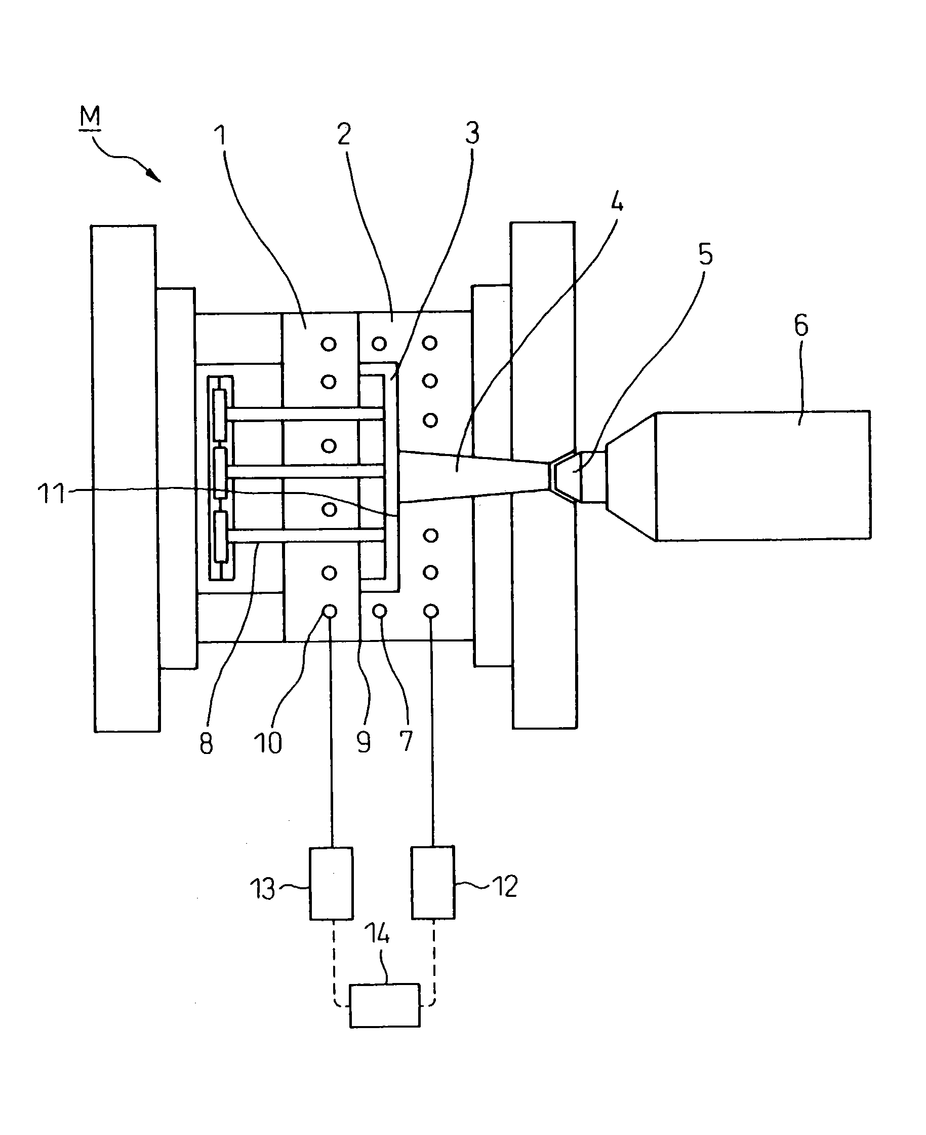
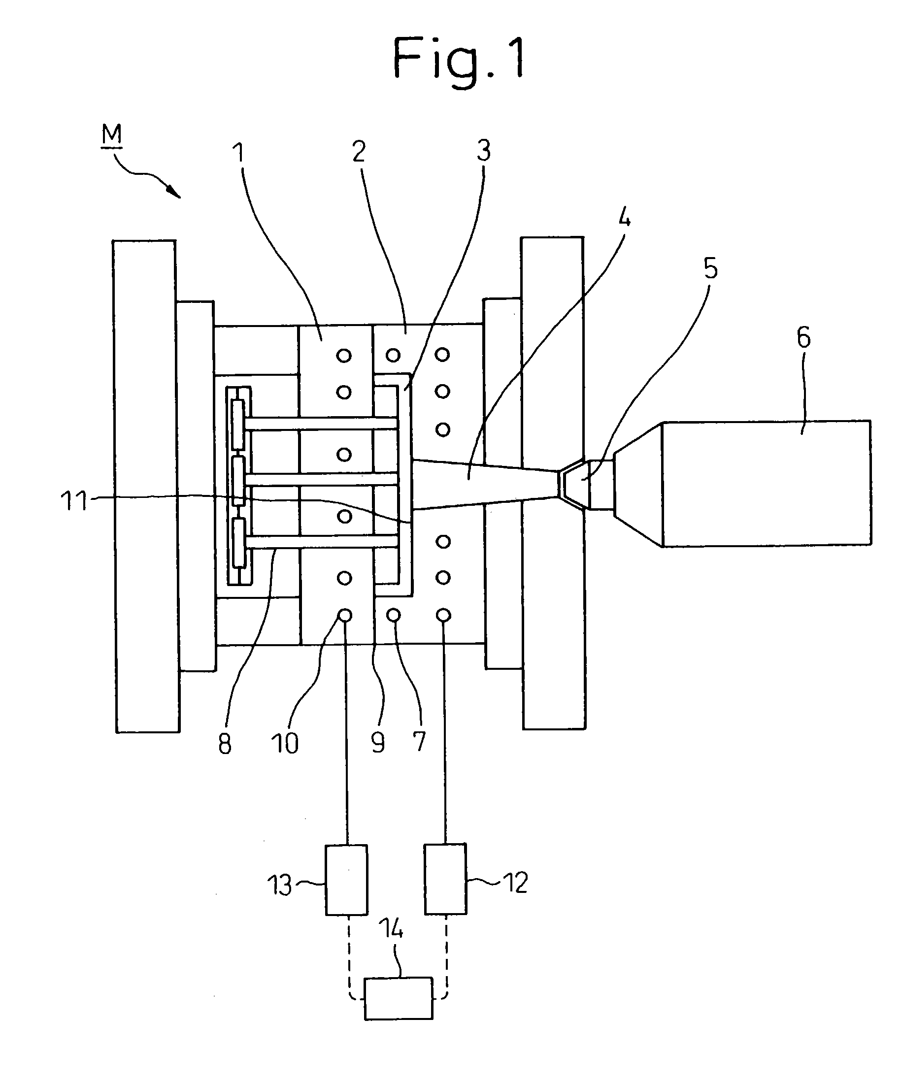
[0016]One embodiment of a mold for a metallic product and a method for controlling the mold temperature according to the present invention will be described below with reference to the attached drawings. FIG. 1 is an elevational sectional view of one embodiment of the inventive mold for molding a metallic product. A device for molding a metallic product has a mold M for molding a metallic product constituted by a movable mold section 1 and a fixed mold section 2. This mold M defines a cavity 3 for molding a metal such as magnesium alloy by clamping the movable mold section 1 and the fixed mold section 2.

[0017]The movable mold section 1 is provided with a motorized or hydraulic mold-driving mechanism (not shown) for advancing / returning it relative to the fixed mold section 2. Accordingly, when the movable mold section 1 advanced, the mold M is closed and, when returned, the mold M is open. Also, ejector pins 8 are provided in the movable mold section 1 for removing a molded product f...


PUM

PropertyMeasurementUnit
temperatureaaaaaaaaaa

Abstract

A mold M for molding a metallic product including a fixed mold section 2 and a movable mold section 1, wherein heating means 7 is provided in the fixed mold section and cooling means 10 is provided in the movable mold section, which means are controlled by a temperature control device 14 so that any desired temperature is obtainable. Also, as the heating and the cooling of the mold are not repeated, but the fixed mold section is always heated and the movable mold section is always cooled, it is possible to shorten the cycle times.

Description

BACKGROUND OF THE INVENTION[0001]1. Field of the Invention[0002]The present invention relates to a mold and method for molding a metallic product capable of easily controlling the temperature of a molten metal during and after the filling of the molten metal into a cavity.[0003]2. Description of the Related Art[0004]There is a prior art disclosed in Japanese Unexamined Patent Publication No. 2001-18229 entitled “Mold for Molding Synthetic resin and Device and Method for Controlling Mold Temperature”. In this prior art, to easily switching the heating and the cooling of a cavity surface of the mold, a liner having a flow path is provided in a mold base, so that a hot medium is made to flow in the flow path when the molten resin is injected, on one hand, and a coolant is made to flow in the flow path thereafter to solidify a product molded within the mold, on the other hand.[0005]When the material to be molded is synthetic resin, as an environment in which the resin is not solidified ...

Claims


Application Information

Patent Timeline
Patent Type & Authority Patents(United States)
IPC IPC(8): B22D17/00B22D17/22B22D17/32
CPCB22D17/2218
Inventor SUZUKI, HIDEYUKISATO, KOICHIRO
Owner DENSO CORP
Why Eureka
Try Eureka