
Cap device

a technology of cap and ring, which is applied in the direction of liquid handling, sealing, packaging goods types, etc., can solve the problems of lowering the rotating performance of the rotation ring, and achieve excellent flexibility and sliding properties, excellent sliding properties, and low liquid swelling resistance.

Inactive Publication Date: 2006-04-11
TOYODA GOSEI CO LTD
View PDF8 Cites 29 Cited by
  • Summary
  • Abstract
  • Description
  • Claims
  • Application Information

AI Technical Summary

Benefits of technology

The solution ensures the fuel cap remains operable and securely attached to the tank, preventing misalignment and ensuring smooth opening and closing operations even in wet conditions, thus preventing the cap from being missed during fuel supply.

Problems solved by technology

This undesirably lowers the rotating performance of the rotation ring 212 and may cause a trouble in rotating operations of the fuel cap 200.

Method used


Image

  • Cap device
  • Cap device
  • Cap device

Examples


Embodiment Construction

[0053](1) General Structure of Fuel Cap 10

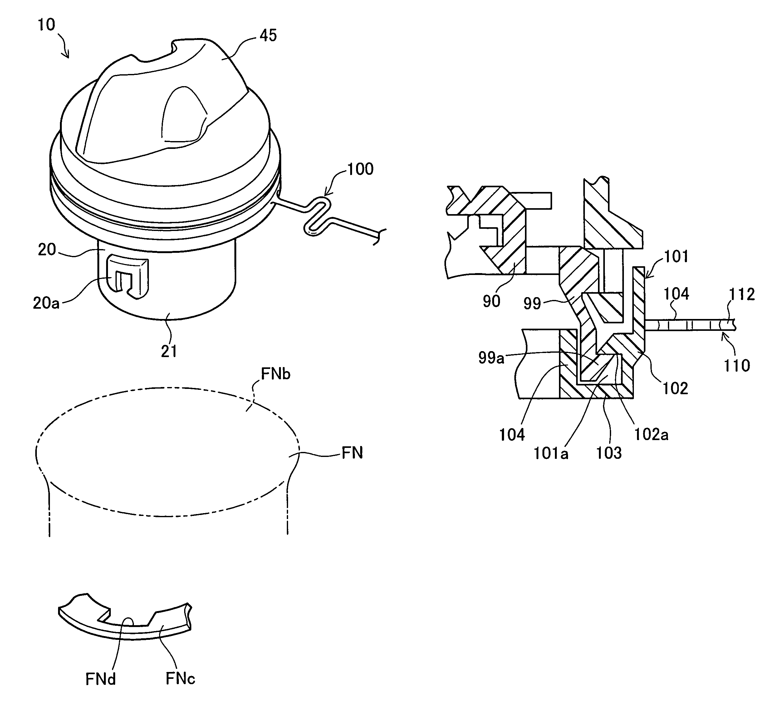
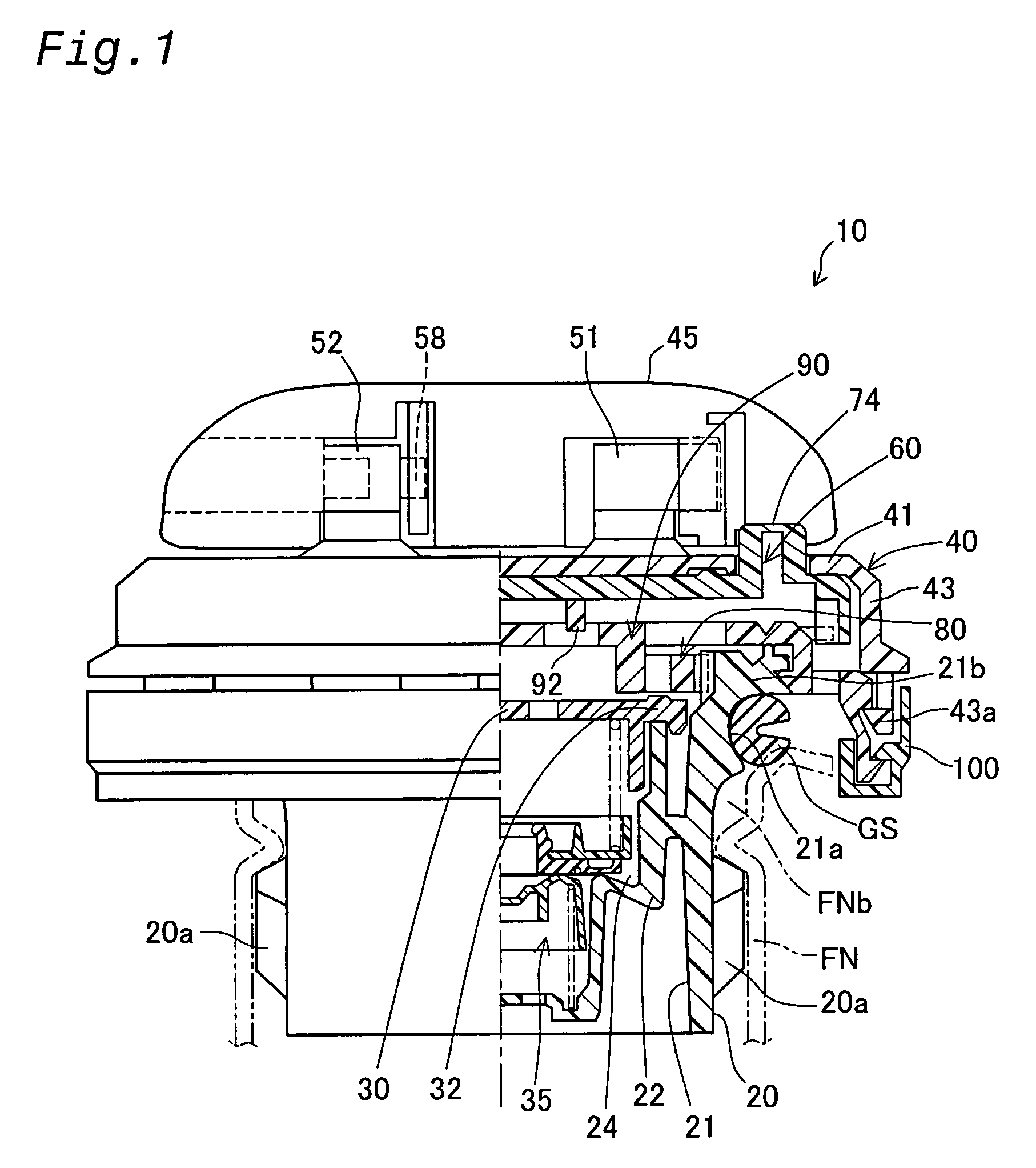
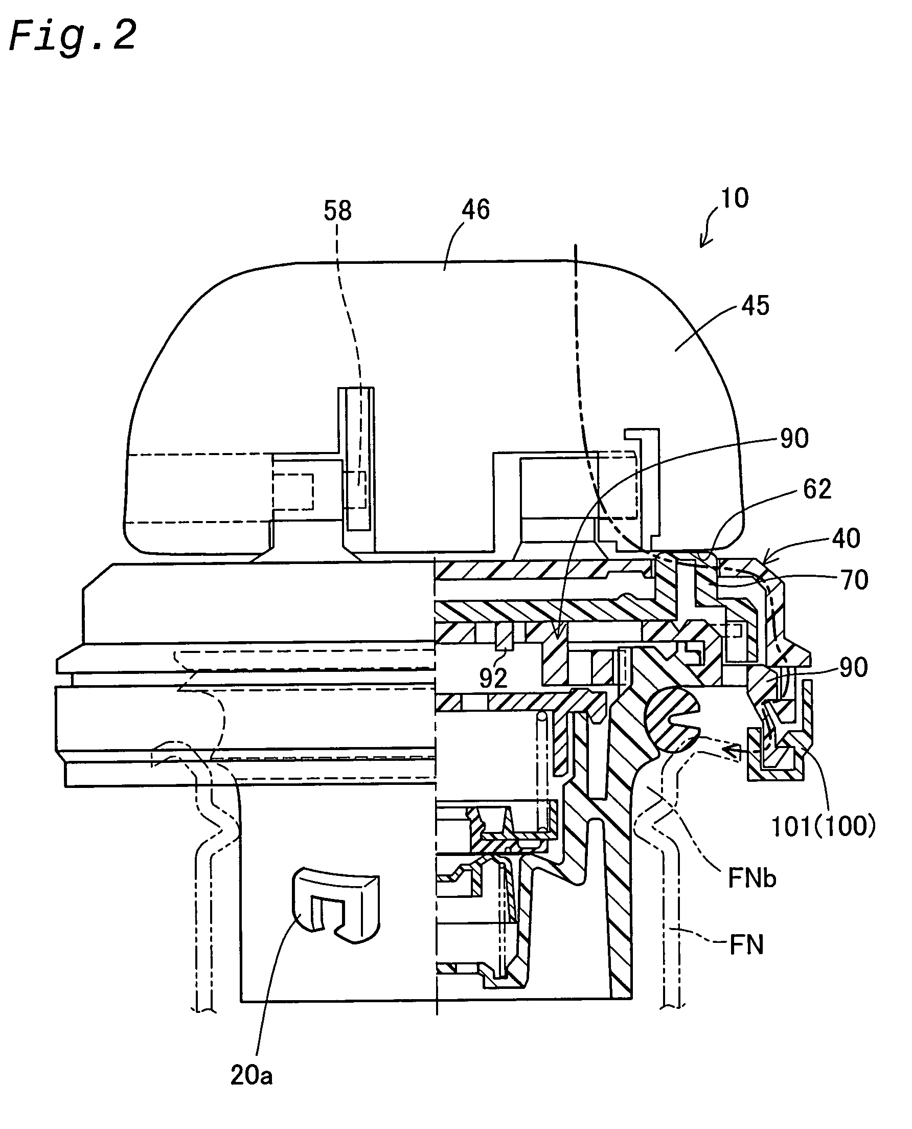
[0054]FIG. 1 is an illustrative diagram showing in partial cutaway a cap device comprising a fuel cap 10 (cap) pertaining to a first embodiment of the invention. In FIG. 1, the fuel cap 10 is attached to a filler neck FN having a filler opening FNb (tank opening) for supplying fuel to a fuel tank, not shown. The cap 10 comprises a casing body 20 (closer) made of polyacetal or other synthetic resin material, an inner cover 30 closing the upper opening of the casing body 20, forming a valve chamber 24; a regulator valve 35 housed within the valve chamber 24; a cover 40 made of nylon or other synthetic resin and mounted on the upper portion of the casing body 20; a handle 45 mounted on the upper face of the cover 40; a clutch mechanism 60 and the torque transmission mechanism 80 (interconnecting mechanism); a tether mechanism 100; and a gasket GS installed on the outside rim of the upper portion of the casing body 20 to provide a seal between t...


PUM

PropertyMeasurementUnit
angleaaaaaaaaaa
angleaaaaaaaaaa
torqueaaaaaaaaaa

Abstract

A fuel cap has a torque member that is attached to a casing body in a freely rotatable manner. A tether mechanism is attached to the torque member and functions to link the fuel cap with a fuel lid. The tether mechanism includes a tether rotation support that is set on the torque member in a freely rotatable manner, and a connector member. The torque member is mainly composed of a resin material, for example, polyacetal, whereas the tether rotation support is mainly composed of a thermoplastic elastomer (TPEE). The resin material of the torque member has a liquid swelling property substantially equal to or less than that of the tether rotation support. This structure of the invention ensures the good operation ability of the fuel cap even in wet weather.

Description

[0001]This application claims the benefit of and priority from Japanese Applications No. 2002-212785 filed Jul. 22, 2002 and No. 2002-283762 filed Sep. 27, 2002, the contents of which are incorporated herein by reference.BACKGROUND OF THE INVENTION[0002]1. Field of the Invention[0003]The present invention relates to a cap device having a long connector member, which is linked with a cap on one end thereof[0004]2. Description of the Related Art[0005]In a fuel tank of a vehicle, a known structure to prevent a fuel cap from being missed at the time of fuel supply uses a long connector member like a tether to link the fuel cap with a periphery of a fuel inlet of the fuel tank. One example of such a fuel cap with a tether is disclosed in JP No. 2002-12044A.[0006]As shown in FIG. 38, a fuel cap 200 has a cover 204 with a handle 204a, which is mounted on an upper portion of a casing body 202 in a freely rotatable manner. A tether mechanism 210 is attached to a circumference of a side wall ...

Claims


Application Information

Patent Timeline
Patent Type & Authority Patents(United States)
IPC IPC(8): B65D55/16B60K15/04
CPCB60K15/0406Y10S220/33B60K2015/03401
Inventor HAGANO, HIROYUKINAKAGAWA, MASAYUKI
Owner TOYODA GOSEI CO LTD
Learn More