Fluid discharge pump for discharging fluid stored inside fluid storing portion
a technology of fluid storage and discharge pump, which is applied in the direction of instruments, single-unit apparatuses, machines/engines, etc., can solve the problems of high production cost, and achieve the effect of low production cost and simple configuration
- Summary
- Abstract
- Description
- Claims
- Application Information
AI Technical Summary
Benefits of technology
Problems solved by technology
Method used
Image

Examples
embodiment 1
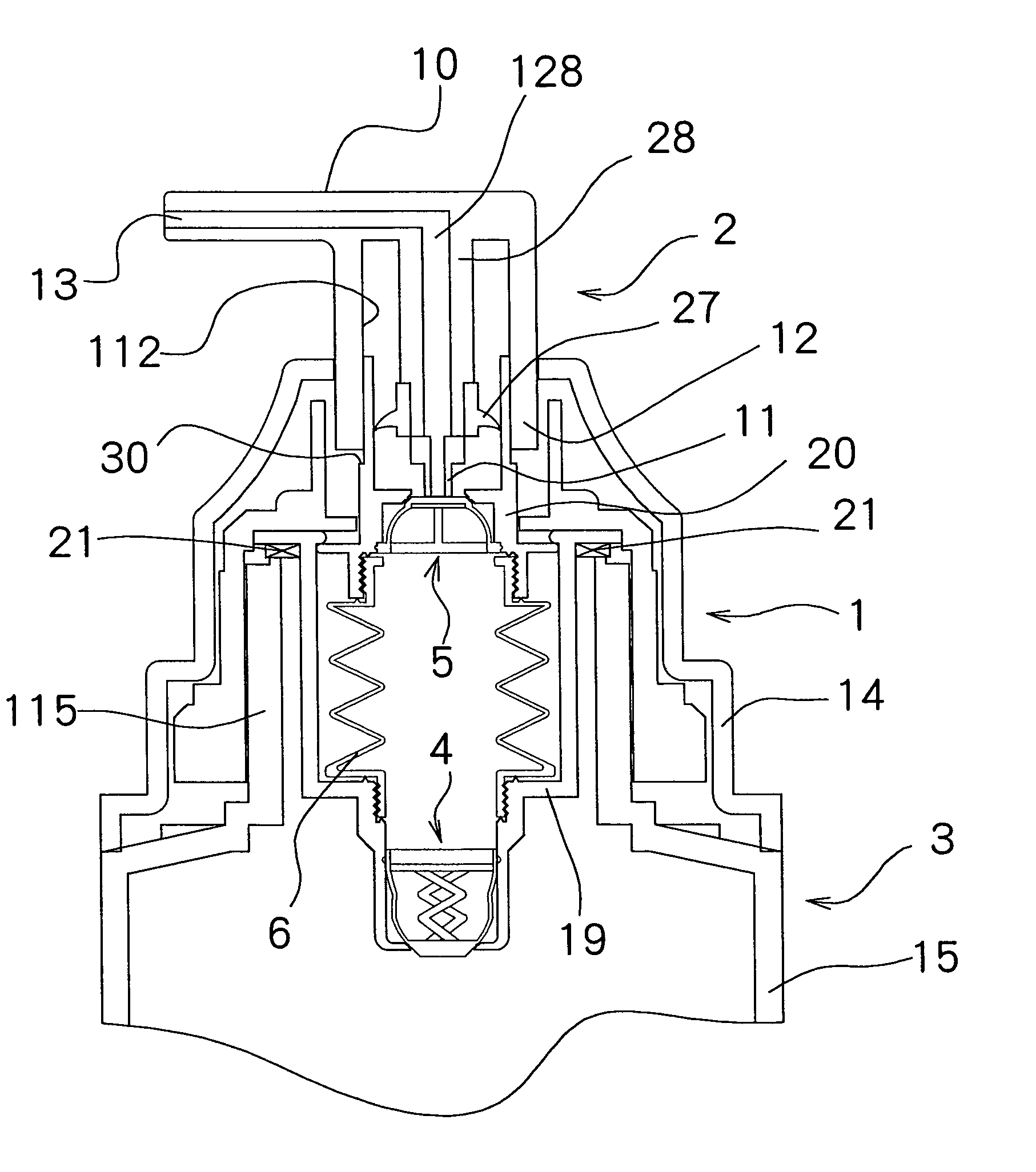
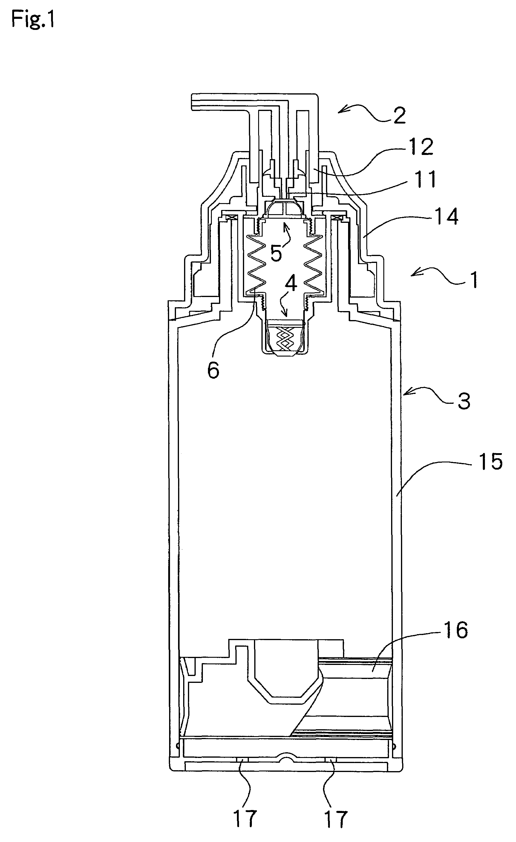
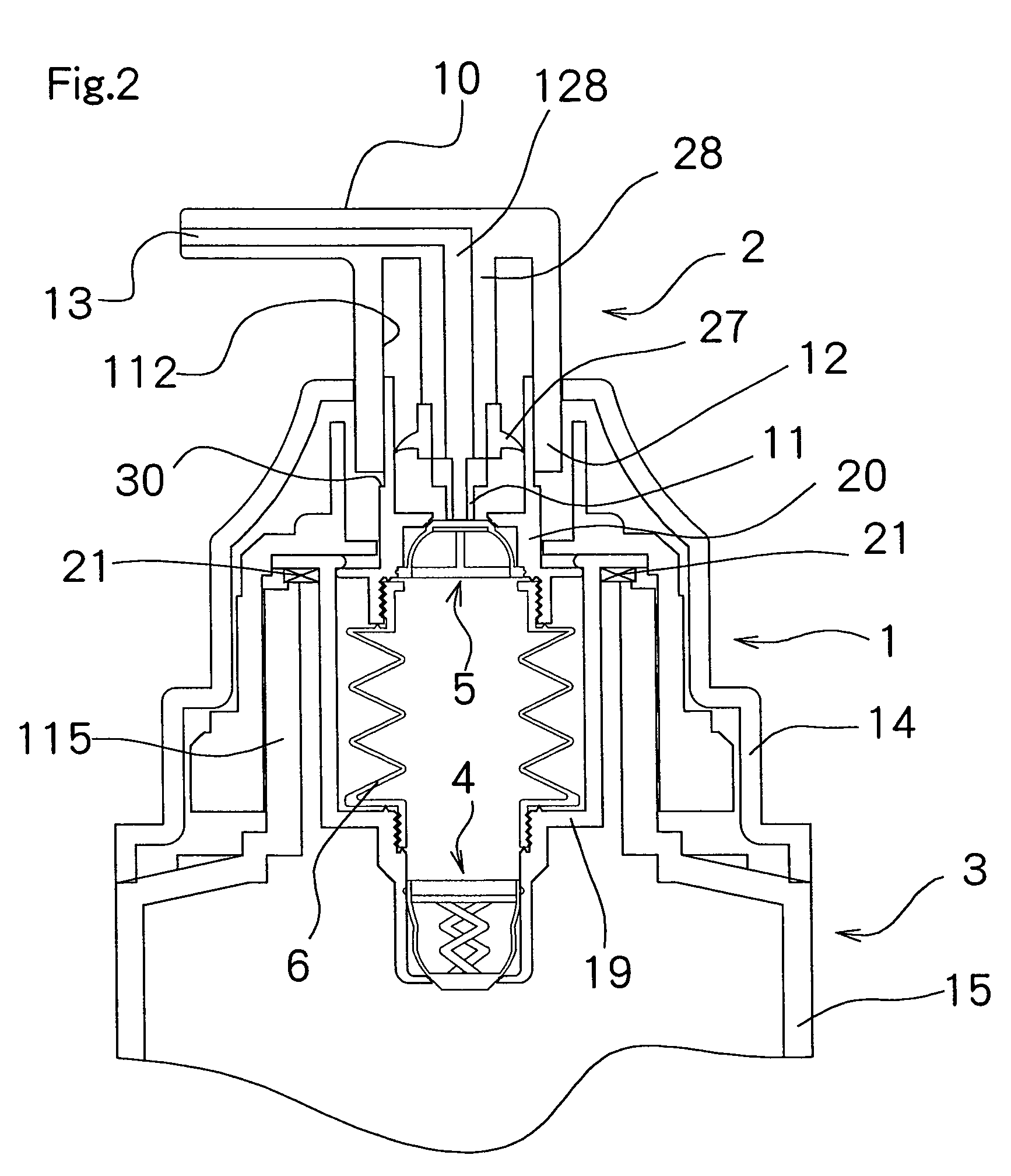
[0038]Preferred embodiments of the present invention are described with referent to the drawings. FIG. 1 is a longitudinal section of a liquid container to which the fluid discharge pump 1 according to the present invention applies; FIG. 2 to FIG. 5 are enlarged views showing its relevant part.
[0039]Of these diagrams, FIG. 1 and FIG. 2 respectively show positions in which the liquid discharge pump 1 is left with no stress applied; FIG. 3 shows a position in which the first pressing portion 11 in a nozzle head 2 presses a valve portion 46 in an outflow valve mechanism 5; FIG. 4 shows a position in which a bellows material 6 is in the process of going to a folded-up position from a stretched position by being pressed by the second pressing portion 12 in the nozzle head 2; FIG. 5 shows a position in which the bellows material 6 is in the process of going to the stretched position from the folded-up position with the nozzle head 2 being opened.
[0040]This liquid container is used as a co...
embodiment 2
[0091]Liquid discharge motions by a liquid discharge container possessing the liquid discharge pump 1 are described below.
[0092]In an initial position as shown in FIG. 13, the bellows material 106 is in the stretched position by the elastic force of the bellows material 106. In this position, a relatively large amount of liquid is stored inside the bellows material 106.
[0093]When the head portion 10 in the nozzle head 102 is pressed in this position, the valve portion 62 of the valve material 60 is first pressed by the first pressing portion 51 as shown in FIG. 14; the valve portion 62 moves to the separated position in which the valve portion is separated from the opening portion in the valve seat material 53. By this, a flow path leading to the discharge portion 13 in the nozzle head 102 from inside the bellows material 106 is formed.
[0094]When the head portion 10 in the nozzle head 102 is pressed further in this position, the second pressing portion 52 in the nozzle head 102 con...
PUM
 Abstract
Description
Claims
Application Information
 - Generate Ideas
- Intellectual Property
- Life Sciences
- Materials
- Tech Scout
- Unparalleled Data Quality
- Higher Quality Content
- 60% Fewer Hallucinations
Browse by: Latest US Patents, China's latest patents, Technical Efficacy Thesaurus, Application Domain, Technology Topic, Popular Technical Reports.
© 2025 PatSnap. All rights reserved.Legal|Privacy policy|Modern Slavery Act Transparency Statement|Sitemap|About US| Contact US: help@patsnap.com