Mold base assembly

a mold base and assembly technology, applied in the field of base assembly, can solve the problems of non-uniform cooling of the mold base, blockage in one of the radial passageways, etc., and achieve the effects of enhancing heat transfer, increasing fluid flow, and enhancing heat transfer

Inactive Publication Date: 2006-04-11
WENTWORTH MOLD
View PDF19 Cites 28 Cited by
  • Summary
  • Abstract
  • Description
  • Claims
  • Application Information

AI Technical Summary

Benefits of technology

[0007]The continuous or serial fluid passageway of the present invention has advantage over the parallel radical passageways of the prior art because by utilizing a continuous fluid passageway in the base insert and co-operating flow divider plate any blockage in the passageway may be detected by the pumping system for the cooling fluid. Further, advantage is found in the base assembly because the passageways are not drilled through the base insert but instead are machined from one face of the insert and one face of the flow divider plate thereby providing a fluid cooling passageway pattern that is able to cover more surface area of the mold face of the base insert. This feature consequently enhances heat transfer between the mold face and fluid passing along the continuous fluid passageway to better cool or heat the base insert over its mold face.
[0012]The base insert has a contoured shape on an upper surface portion that corresponds to the shape of the base of the container to be formed. This contoured upper surface portion may have a series of indentations representing container feet. It is envisaged that the cavities extend into the base insert between these indentations to enhance heat transfer around the surfaces of the feet to be formed in the base of the container.
[0013]To further enhance heat transfer, the continuous fluid passageway may have a cross-sectional area that varies along the passageway to increase turbulence of the fluid flowing along the passageway.

Problems solved by technology

These parallel radial flow passageways may not have equal flow of coolant there through, in practice, possibly resulting in non-uniform cooling of the mold base.
Further, any blockage in one of the radial passageways may go undetected because the other passageways continue to function.

Method used


Image

  • Mold base assembly
  • Mold base assembly
  • Mold base assembly

Examples


Embodiment Construction

[0024]Referring to the drawings the embodiments of the present invention are described. While the mold apparatus described herein is adapted for making a cold fill PET bottle, it should be understood that the mold apparatus shown can be used for other types of containers when the mold face is changed, such as for example, water, soft drinks, juices, cleansers, and detergent type containers to name a few.

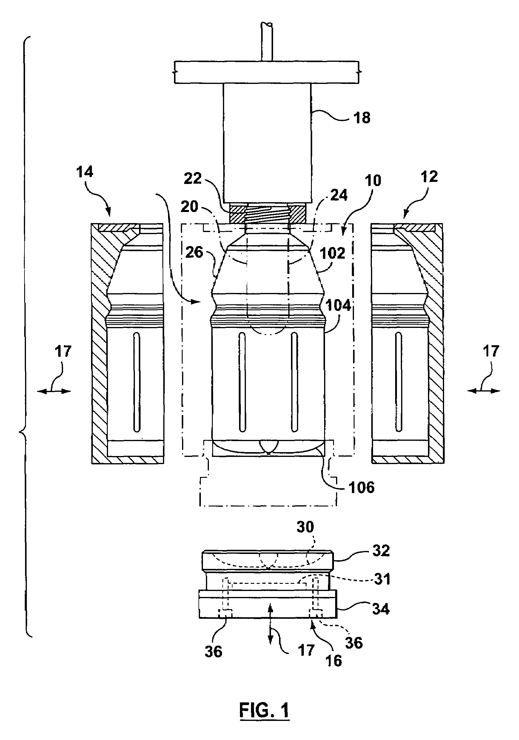
[0025]In FIG. 1, the bottle 100 is made from a preform 20 having a thread finish 22 attached to carrier 18 and a lower tube portion 24 which is blown into a bottle shape in a mold 10. During blowing the preform assumes the shape of the interior molding surface 26 of the mold to form an upper shoulder portion 102, a middle label panel portion 104, and a base 106. The upper shoulder 102 flares radially outwardly from the relatively narrow tube portion 24 to the label panel 104.

[0026]The modular mold assembly shown in FIG. 1 includes three movable mold parts 12, 14, and 16 which come to...


PUM

PropertyMeasurementUnit
shapeaaaaaaaaaa
wear resistantaaaaaaaaaa
weightaaaaaaaaaa

Abstract

A base assembly used as a part of a mold assembly for forming a container has a base insert and a flow divider plate that co-operate to define a continuous fluid passageway for cooling or heating the base insert. The flow divider plate has an upper surface portion having at least one raised runway extending in a first pattern covering a substantial area of the upper surface portion. The base insert has a lower surface portion with a continuous channel extending in a second pattern. The channel is positioned adjacent the at least one raised runway in sealing relation therewith to define a continuous fluid passageway.

Description

FIELD OF THE INVENTION[0001]The present invention relates to a base assembly for use as part of a modular mold for making containers, and more particularly to the cooling / heating passageways utilized in such a base assembly.BACKGROUND OF THE INVENTION[0002]Mold assemblies comprising two side mold parts and a base mold part are commonly used in the formation of plastic containers such as, for example, biaxially-oriented PET (polyethylene terephthalate) beverage bottles. The side mold parts may comprise a unitary half-part, multiple half-parts or a shell half insert. The base part of the mold assembly is typically manufactured from a steel adaptor plate and a cast steel or cut steel base insert that is inserted into the mold assembly.[0003]The base insert is formed with a base mold face having a pattern or impression corresponding to the bottle to be formed. The adaptor plate is typically a cylindrical shaped plate to which the base insert is secured by threaded screws or bolts. The b...

Claims


Application Information

Patent Timeline
Patent Type & Authority Patents(United States)
IPC IPC(8): B29C49/64B29C49/06B29C49/48
CPCB29C49/4823B29C49/06B29C2049/4892B29C2049/4843B29C2049/4889B29C2049/4828B29C2049/4825B29C2049/4848B29C2949/0715
Inventor TSAU, TAR
Owner WENTWORTH MOLD
Why Eureka
Try Eureka