Thin, flexible actuator array to produce complex shapes and force distributions

Inactive Publication Date: 2006-09-14
MASSACHUSETTS INST OF TECH
View PDF6 Cites 27 Cited by
  • Summary
  • Abstract
  • Description
  • Claims
  • Application Information

AI Technical Summary

Benefits of technology

[0017] Moreover, the separate wires can have more surface area which can allow better contact with laminating adhesive to avoid wire pull-out, and can dissipate heat more rapidly compared to larger pieces of shape memory alloy. High surface area per unit volume can allow a higher actuation frequency.
[0018] Also, the shape memory elements in the disclosed inventions are discrete. Compared to devices wherein adjacent actuators are formed from a continuous piece of shape memory alloy, the disclosed inventions can be more isolated and thus can experience less thermal cross talk.
[0019] Moreover, coupling two shape memory elements with a bistable mechanism allows the actuator to maintain a position while shut off after actuation, which can minimize power consumption and heat production compared to existing devices. This can be particularly beneficial for devices intended to operate in power or temperature sensitive environments, such as handheld massagers, massa

Problems solved by technology

However, such designs lack a second stable position as in a bistable mechanism.
Discontinuous cantilevers can be undesirable, however, for applications needing a smooth surface on the bistable mechanism.
However, common materials typically limit the height of the dome to about 10% of its diameter, and consequently the maximum throw can be limited to about twice the dome height (hence, about 20% of a diameter).
These designs can require assembly and one or more additional parts for proper function, and can have limitations similar to dome-like mechanisms.
Moreover, the rigid support can be unsuitable for applications requiring flexibility and/or for macroscopic applications where the added weight of the rigid sup

Method used


Image

  • Thin, flexible actuator array to produce complex shapes and force distributions
  • Thin, flexible actuator array to produce complex shapes and force distributions
  • Thin, flexible actuator array to produce complex shapes and force distributions

Examples


Embodiment Construction

[0043] The foregoing and other objects, features and advantages of the invention will be apparent from the following more particular description of preferred embodiments of the invention, as illustrated in the accompanying drawings in which like reference characters refer to the same parts throughout the different views. The drawings are not necessarily to scale, emphasis instead being placed upon illustrating the principles of the invention. A description of preferred embodiments of the invention follows.

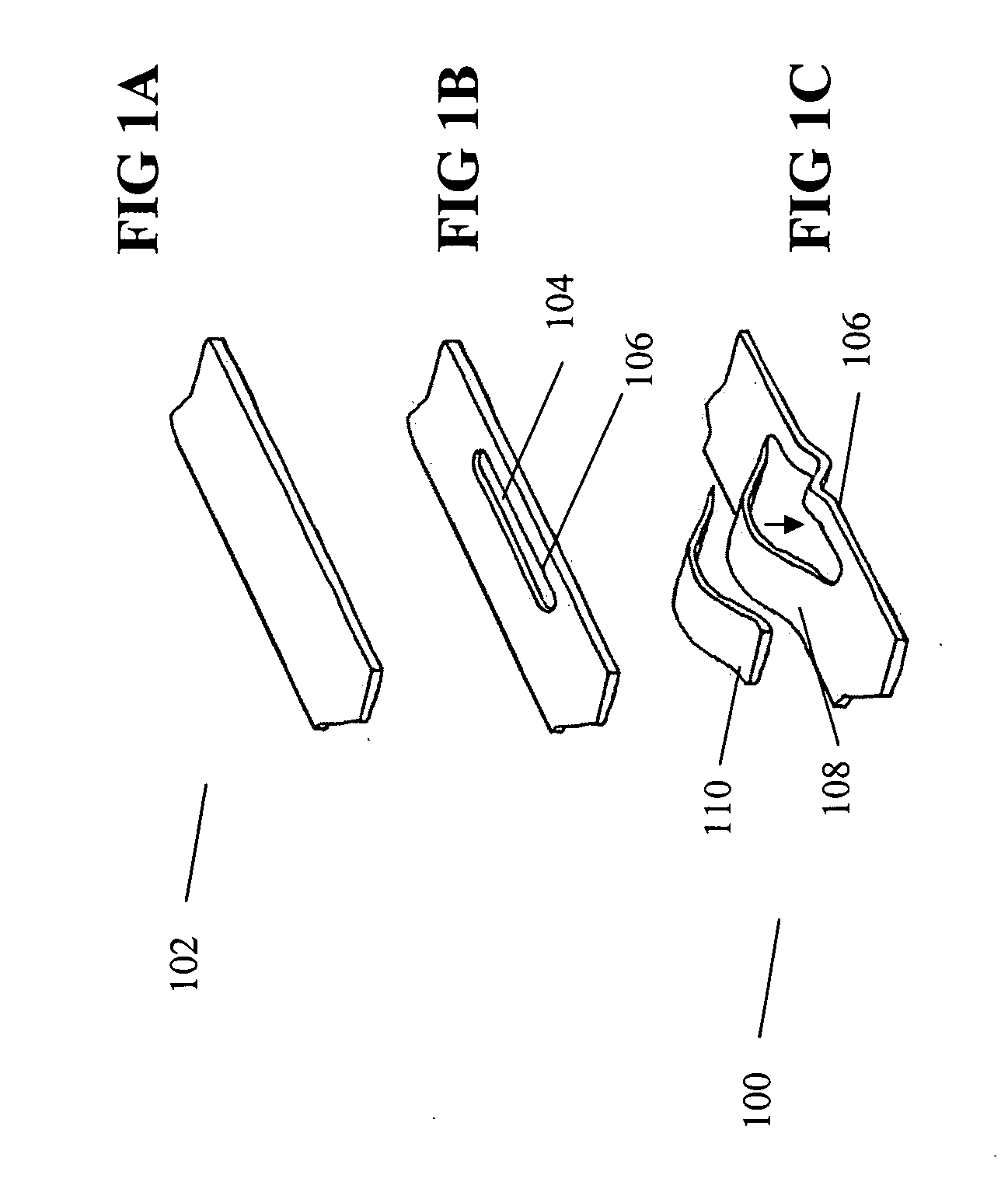
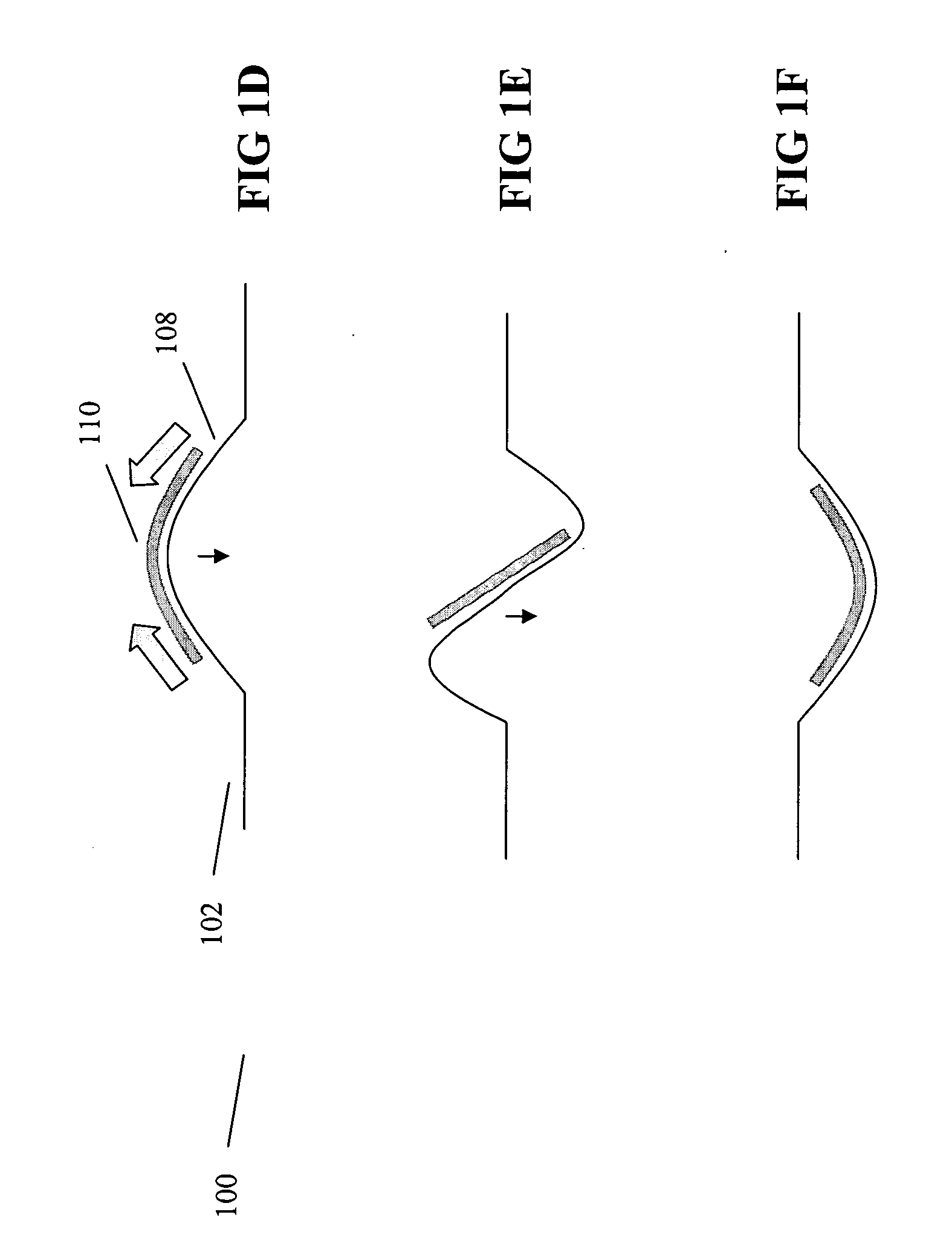
[0044]FIGS. 1A, 1B, 1C and 1C are drawings showing (FIG. 1A) a flexible substrate 102; (FIG. 1B) a relief slit 104 formed in flexible substrate 102 and (FIG. 1C) an exploded view of an actuator 100 wherein relief slit 104 defines a tension beam 106 and a compression beam 108, and the compression beam can be deformed to a first stable position. Also included in FIG. 1C) is a shape memory element 110. Tension beam 106 and compression beam 108 can be formed to be substantially parall...


PUM


Abstract

An actuator includes a bistable mechanism having a tension beam and a compression beam defined by a relief slit in a flexible substrate; and a first shape memory element that upon heating actuates the actuator from a first position to a second position. A heat source can be thermally coupled to actuate the first shape memory element, or the first shape memory element can be heated by passing current through the element. The actuators can be formed in an array. Such arrays can be useful for tactile displays, massagers, and the like. Also included are methods of operation and manufacturing.

Description

GOVERNMENT SUPPORT [0001] The invention was supported, in part, by grant N66001-02-C-8802 from the Defense Advanced Research Projects Agency (DARPA). The Government has certain rights in the invention.BACKGROUND OF THE INVENTION [0002] Restoring mechanisms, also known as “overcenter mechanisms,”“snap springs,”“snap blades,” and the like, are components of many devices, including valves and electrical switches. [0003] Monostable mechanisms are known. For example, a rigid support can be overlaid by a membrane with projections that restore push buttons, such as those of a telephone keypad, back to an undepressed position. However, such designs lack a second stable position as in a bistable mechanism. [0004] Discontinuous cantilever bistable mechanisms are known, wherein discontinuous cantilevered tongues are held in relation to each other by a surround fashioned from the same sheet as the cantilevers. These discontinuous cantilevers can impart bistable movement to a notched rod capture...

Claims


Application Information

Patent Timeline
IPC IPC(8): F01B29/10F02G1/04
CPCH01H1/0036H01H37/323H01H61/0107H01H2001/0042H01H2061/006
Inventor BIGGS, S. JAMESDAVERMAN, R. DODGE
Owner MASSACHUSETTS INST OF TECH
Why Eureka
Try Eureka