Ultrasound welding of plastics components

Inactive Publication Date: 2006-04-11
DEGUSSA AG
View PDF13 Cites 33 Cited by
  • Summary
  • Abstract
  • Description
  • Claims
  • Application Information

AI Technical Summary

Benefits of technology

[0012]An object of the invention is to simplify the known process of ultrasound welding

Problems solved by technology

However, the capabilities of a bond resulting from broaching by the above-noted “mandrel” do not meet all requirements, particularly not at high temperatures like those likely to occur in the engine compartment of a motor vehicle.
Under

Method used


Image

  • Ultrasound welding of plastics components
  • Ultrasound welding of plastics components
  • Ultrasound welding of plastics components

Examples


Embodiment Construction

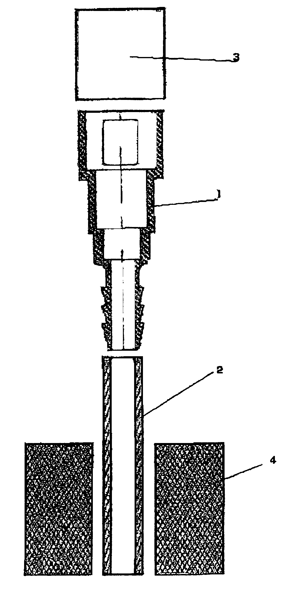
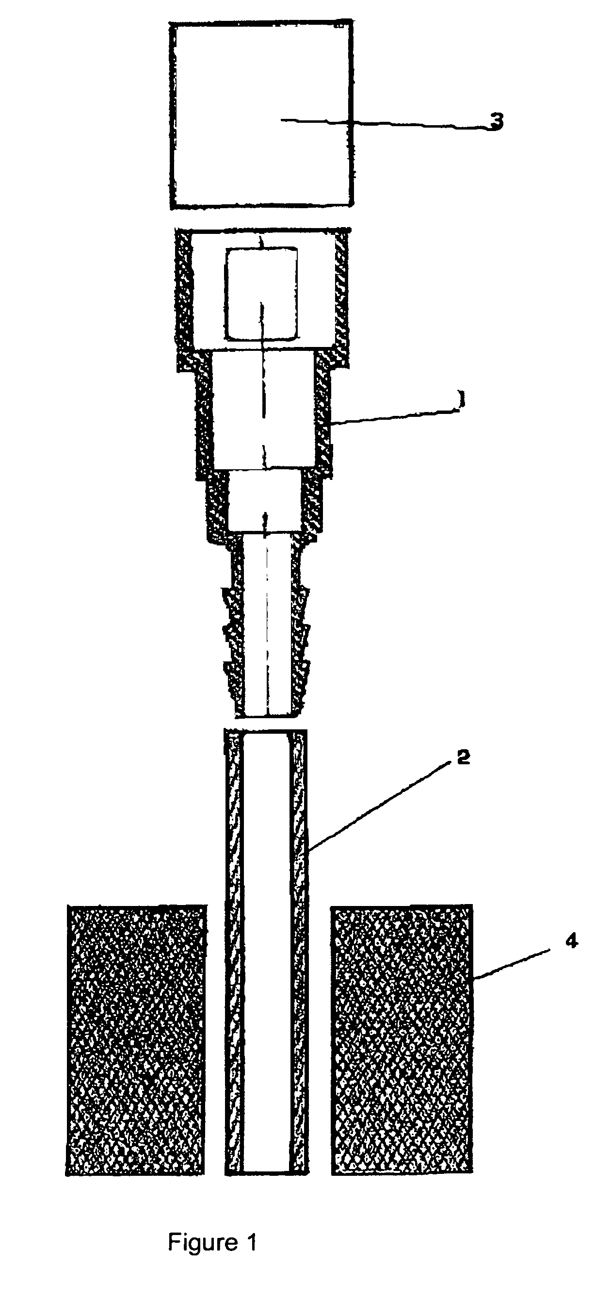
[0020]Referring now to the drawings, wherein like reference numerals designate identical or corresponding parts throughout the several views, and more particularly to FIG. 1 thereof, this figure shows the starting position of the ultrasound welding machine sonotrode (3), the pipe (2) held in fixing system (4) and the other plastics part (1), a quick connector, for example. As further illustrated by FIG. 1, the sonotrode (3), the pipe (2), and the quick connector (1) are initially separated elements.

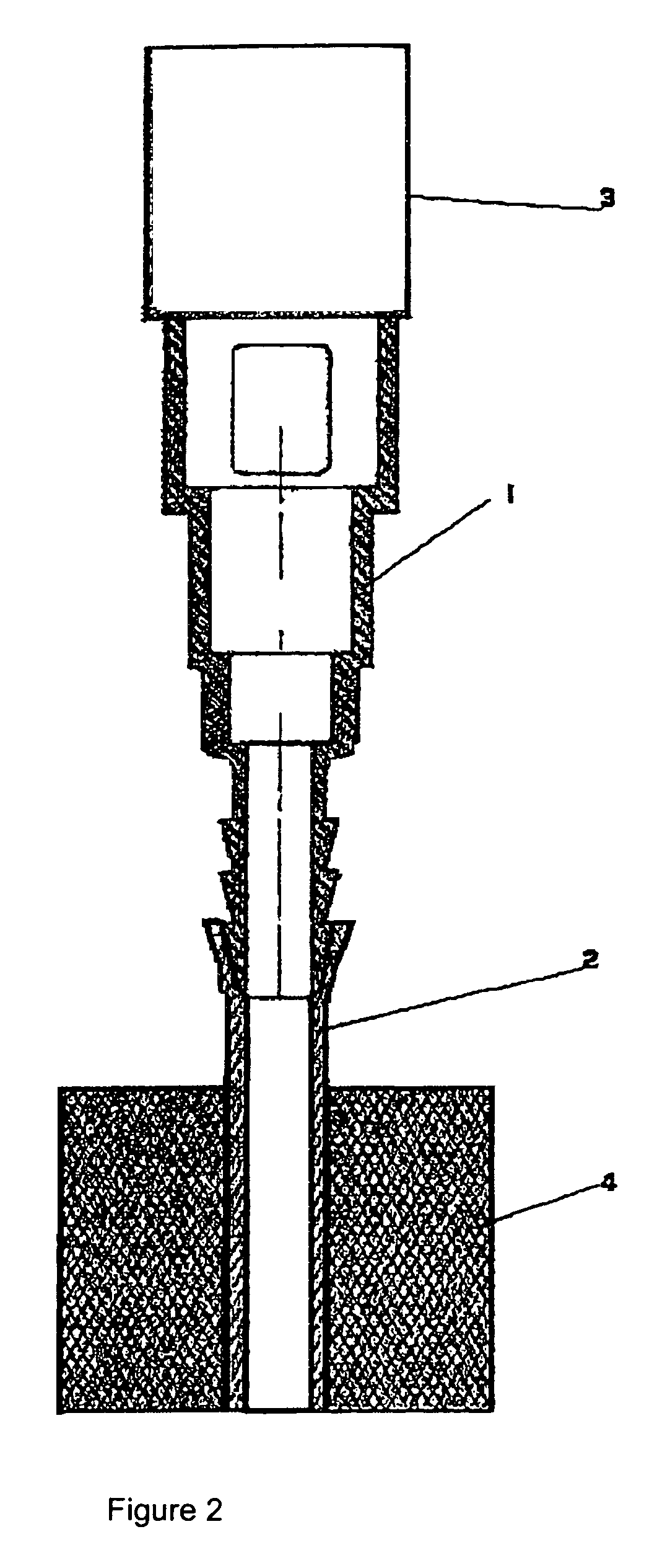
[0021]FIG. 2 illustrates the quick connector (1) beginning to be forced to some extent into the pipe (2) with the aid of the ultrasound welding machine sonotrode (3). This is when exposure to ultrasound from the ultrasound sonotrode (3) begins for the quick connector (1).

[0022]Simultaneously with this exposure to ultrasound, the quick connector (1) is pressed further into the pipe (2) by the welding machine sonotrode (3) as illustrated by FIG. 3. After the welding procedure, the sonotrode...


PUM

PropertyMeasurementUnit
Electrical conductivityaaaaaaaaaa
Exposure limitaaaaaaaaaa

Abstract

A process for the bonding of a plastics pipe to another plastics part by ultrasound welding using sound waves which act longitudinally with respect to the pipe axis, while the arrangement of the areas to be welded is substantially parallel to the pipe axis. The welding procedure is combined with the forced insertion of the other plastics part into the plastics pipe in such a way that there is at least some overlap between the exposure to sound and the forced insertion.

Description

CROSS-REFERENCE TO RELATED APPLICATIONS[0001]This patent document claims priority to German Patent Publication 103 18 3213.3 filed Apr. 19, 2003, the entire contents of which are hereby incorporated herein by reference.BACKGROUND OF THE INVENTION[0002]1. Field of the Invention[0003]The invention relates to a method for the bonding of a single- or multilayer pipeline to another plastics part, e.g. to a quick connector.[0004]2. Discussion of the Background[0005]There are known bonds between a pipe and a plastics part where the plastics part acts as a mandrel broaching the pipe. In this process, the pipe is widened in order to receive the nipple of the plastics part. The pipe then replicates any profile present on the nipple. This bond is required to have maximum resistance to permeation and leakage, to withstand high separation forces, and to resist distortion.[0006]In the case of bonding of a fuel line and a quick connector, the use of a “wedding band” is also known (e.g., see DE 41 ...

Claims


Application Information

Patent Timeline
IPC IPC(8): B32B37/00B23K20/10F16L47/02B29C65/08B29C65/64B29L23/00
CPCB29C65/08B29C66/5344B29C66/8322B29C65/645B29C66/7212B29C66/71B29C66/7392B29C66/612B29C66/1282B29C66/12842B29C66/12862B29C66/1288B29C66/7234B29K2307/04B29K2077/00B29K2309/08B29K2067/00B29K2027/12B29K2023/086B29K2023/00E02B3/06
Inventor MONSHEIMER, SYLVIAGORING, RAINERRIES, HANSBRUDNY, GUNTER
Owner DEGUSSA AG
Why Eureka
Try Eureka