
Method and apparatus for solar power conversion

a technology of solar energy and solar energy, applied in the field of energy conversion, can solve the problems of increasing system amplitude, dramatically reducing efficiency, and never-ending task of producing electricity used by modern societies, and achieve the effect of increasing system overall efficiency

Inactive Publication Date: 2006-04-11
AEROJET ROCKETDYNE OF DE
View PDF10 Cites 31 Cited by
  • Summary
  • Abstract
  • Description
  • Claims
  • Application Information

AI Technical Summary

Benefits of technology

This approach maintains optimal heater head temperature and enhances overall efficiency by adjusting the number and operation of Stirling engines in response to insolation variations, ensuring continuous optimal performance and reduced energy production costs over time.

Problems solved by technology

Therefore producing the electricity used by modern societies is a never-ending task.
The conversion of thermal energy to mechanical within this system would cause such a system have successively higher amplitudes until mechanical interference or some other means of removing the energy appears.
Nevertheless, once a Stirling cycle engine is tuned or optimized for particular operating conditions its efficiency dramatically decreases when these optimum conditions are not maintained.
If the concentrated sunlight entering the absorber cavity varies slightly, the efficiency of the single Stirling cycle engine can be compromised.
Moreover, time of day and seasonal variations can cause the sunlight to travel through more or less atmosphere and effect the insolation, thereby adversely affecting the concentrated solar power level to a value that is not consistent with operating the Stirling cycle engine at its optimum efficiency.
When the insolation becomes too low, the Stirling engine overcools the thermal cavity.
This will result in a reduction in the heater head temperature causing the engine to operate at a lower efficiency point.
Although, the design of the Stirling engine can be modified by adjusting the stroke length to partially compensate for this, the Stirling engine still may not operate at optimum or designed conditions.
Therefore, over a long period of time, this inefficiency can have a significant impact on the life cycle cost of the units of energy produced.

Method used


Image

  • Method and apparatus for solar power conversion
  • Method and apparatus for solar power conversion
  • Method and apparatus for solar power conversion

Examples


Embodiment Construction

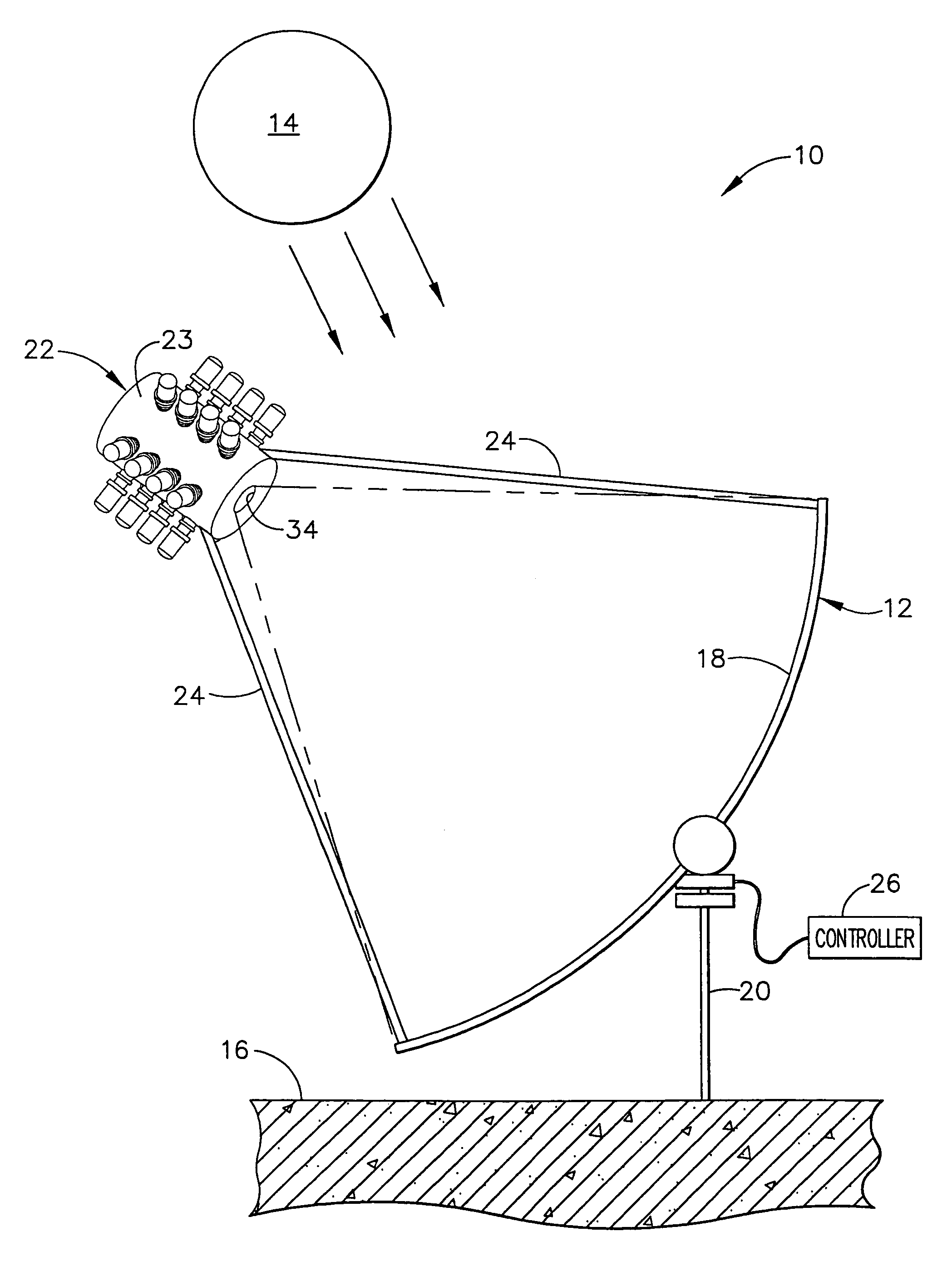
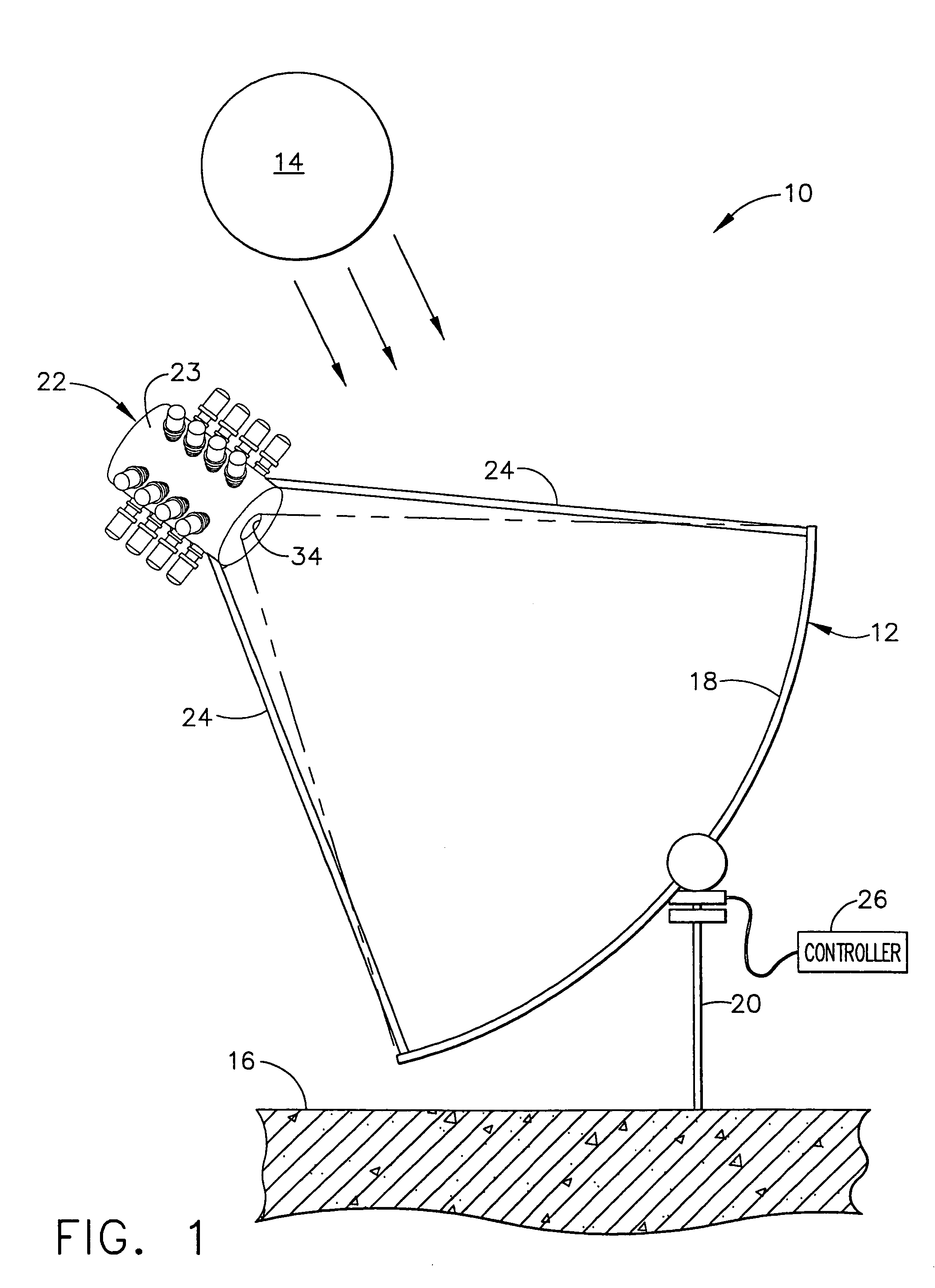
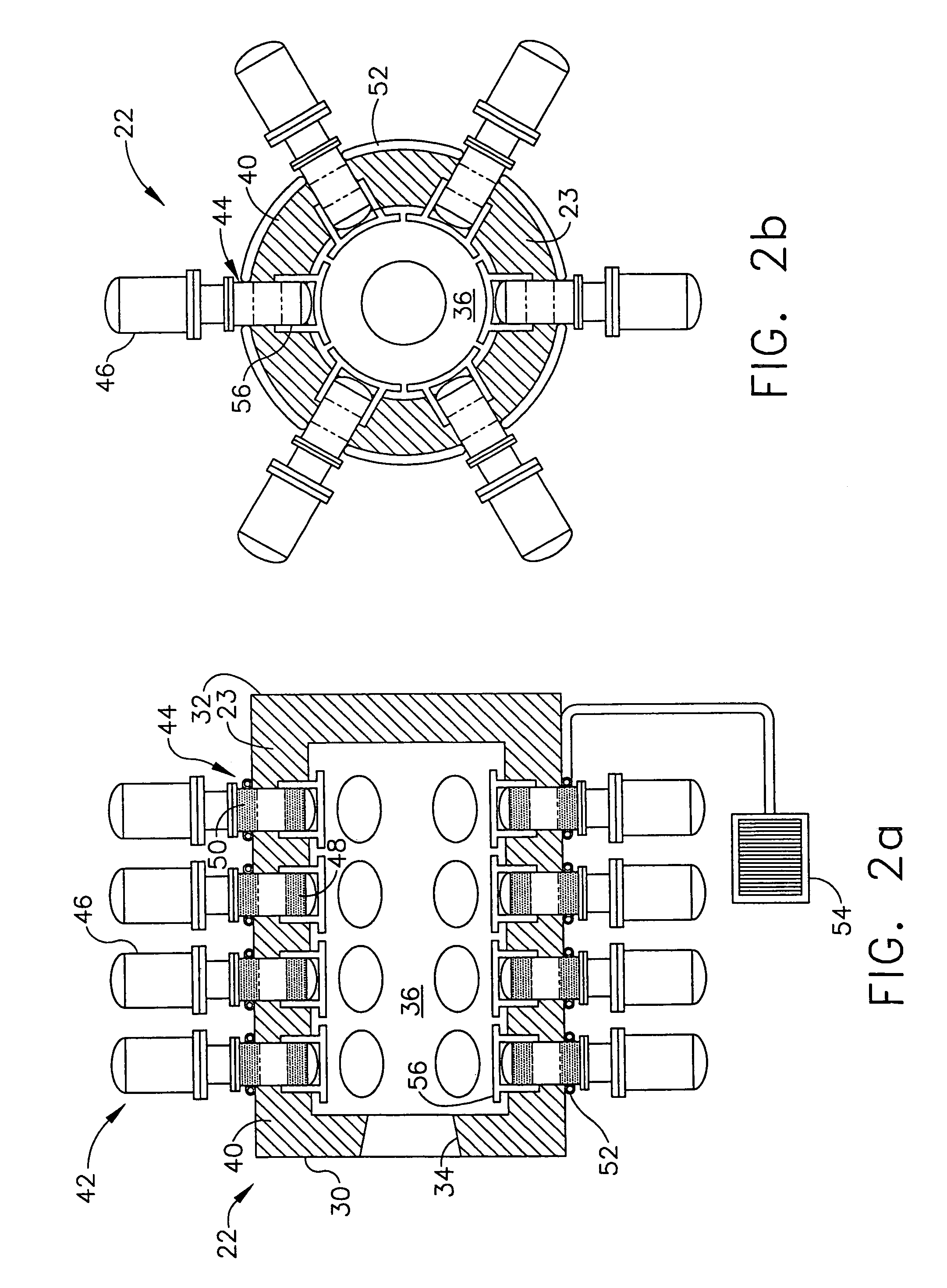
[0026]The following description of the preferred embodiment(s) is merely exemplary in nature and is in no way intended to limit the invention, its application, or uses. Although the following exemplary description describes a terrestrial power generation system using solar energy as the source of thermal energy, it will be understood that a non-terrestrial based system may also be formed. Furthermore, other sources of heat may be used within the scope of the present invention. In addition, although the following description relates specifically to the use of an engine using the Stirling cycle to convert thermal energy into electrical energy, it will be understood that various other engines or cycles can be used. Specifically, engines using various other cycles can be used with the systems described below include the Brayton cycle and the Rankine cycle. These, along with other cycles, can be formed into engines which use the thermal energy collected and concentrated according to the ...


PUM


Abstract

A solar power conversion system using a plurality of engines to convert solar energy to electrical energy. The plurality of engines are supported adjacent to a housing having a single thermal cavity. The cavity is provided with solar energy from a solar collector. Each of the engines can be turned off or regulated to maintain an optimum operating temperature for a common heater head in communication with each of the engines. Therefore, the power conversion system can be regulated for variations in insolation to maintain an optimum temperature in the heater head. Therefore, increased life cycle energy efficiency of the power conversion system can be obtained.

Description

CROSS-REFERENCE TO RELATED APPLICATIONS[0001]This application is a divisional of U.S. patent application Ser. No. 10 / 434,311 filed on May 8, 2003 now U.S. Pat. No. 6,979,911, which is presently allowed. The disclosure of the above application is incorporated herein by reference.FIELD OF THE INVENTION[0002]The present invention relates to energy conversion using concentrated solar energy and solar thermal receivers, and particularly relates to the heating of various heat engines with solar thermal receivers that are in turn heated by solar collectors and concentrators.BACKGROUND OF THE INVENTION[0003]The use of electricity has become more and more inclusive in modern times. Electricity is nearly ubiquitous in every day activities. Therefore producing the electricity used by modern societies is a never-ending task. Various forms of conversion are used to convert naturally occurring energy sources into electricity. One naturally occurring energy source is solar energy. Solar energy can...

Claims


Application Information

Patent Timeline
Patent Type & Authority Patents(United States)
IPC IPC(8): H02K7/18F03G6/06F24S20/20F24S23/71H02P9/04
CPCF03G6/068F24J2/12F24J2/40F24J2/07F02G2254/30F02G2275/00F02G2280/10Y02E10/46Y02E10/41Y02E10/42F24S23/71F24S20/20F24S50/00Y02E10/40
Inventor OTTING, WILLIAM D.KUDIJA, JR., CHARLES T.
Owner AEROJET ROCKETDYNE OF DE
Learn More