Drive system

a technology of drive system and drive shaft, which is applied in the direction of motor/generator/converter stopper, emergency power supply arrangement, process and machine control, etc., can solve the problems that the brake resistor b>26/b> may require a considerable amount of space, and achieve the effect of reducing the complexity of the energy recovery device and its electrical connection

Active Publication Date: 2006-04-11
SIEMENS AG
View PDF36 Cites 26 Cited by
  • Summary
  • Abstract
  • Description
  • Claims
  • Application Information

AI Technical Summary

Benefits of technology

[0011]The energy recovery device returns energy from the buffer capacitor at the output-side of the central power supply to the power line and regulates the voltage at the buffer capacitor to a predetermined value. The energy recovery device eliminates the conventional brake circuit, which is not only less expensive and saves space, but also significantly improves the overall efficiency of the drive system.
[0012]According to an advantageous feature of the drive system, the energy recovery device can include a second DC / DC converter and a line-commutated bidirectional converter, whereby an input of the second DC / DC converter can be connected to the input terminals of the energy recovery device and a DC output of the second DC / DC converter can be connected to the DC-side of the line-commutated bidirectional converter. With this embodiment, energy can be returned to the power line even if the regulated DC voltage at the output-side capacitor of the central power supply is lower than an equivalent DC value of the line voltage of the power line. The DC / DC converter generates from the regulated output DC voltage of the central power supply a DC voltage with an amplitude that is greater than the equivalent DC value of the power line voltage, allowing current to flow from the line-commutated bidirectional converter back into the power line. The drive system of the invention can be used with a modular transport system.
[0013]According to another advantageous feature of the drive system, the second DC / DC converter can include an auxiliary power supply, which can be used to supply power to a controller of the line-commutated bidirectional converter. The auxiliary power supply can include an auxiliary winding of the DC / DC converter and a diode connected downstream of the auxiliary winding. This arrangement also makes the energy recovery device less expensive, because the controller of the line-commutated bidirectional converter no longer requires an external power supply.
[0017]This arrangement with a line-commutated bidirectional rectifier significantly reduces the complexity of the energy recovery device and its electrical connection with the drive system, because only the DC / DC converter in the central power supply, which is not capable of energy recovery, has to be bridged for returning energy from the various loads (motors) to the power line. The DC / DC converter can convert the voltage applied to the output-side capacitor into a DC voltage with an amplitude that exceeds the equivalent DC value of the power line voltage by a predetermined value. Energy can then be returned to the power line even if the regulated DC voltage at the output-side capacitor of the central power supply is smaller than an equivalent DC value of the power line voltage. In this way, a current can flow from the capacitor across the output of the central power supply through the line-commutated bidirectional rectifier to the power line. This drive system of the invention is also suitable for use with a modular transport system. The DC / DC converter can be a flyback converter or a flux converter.

Problems solved by technology

In addition, the brake resistor 26 may require a considerable amount of space.

Method used


Image

  • Drive system
  • Drive system
  • Drive system

Examples


first embodiment

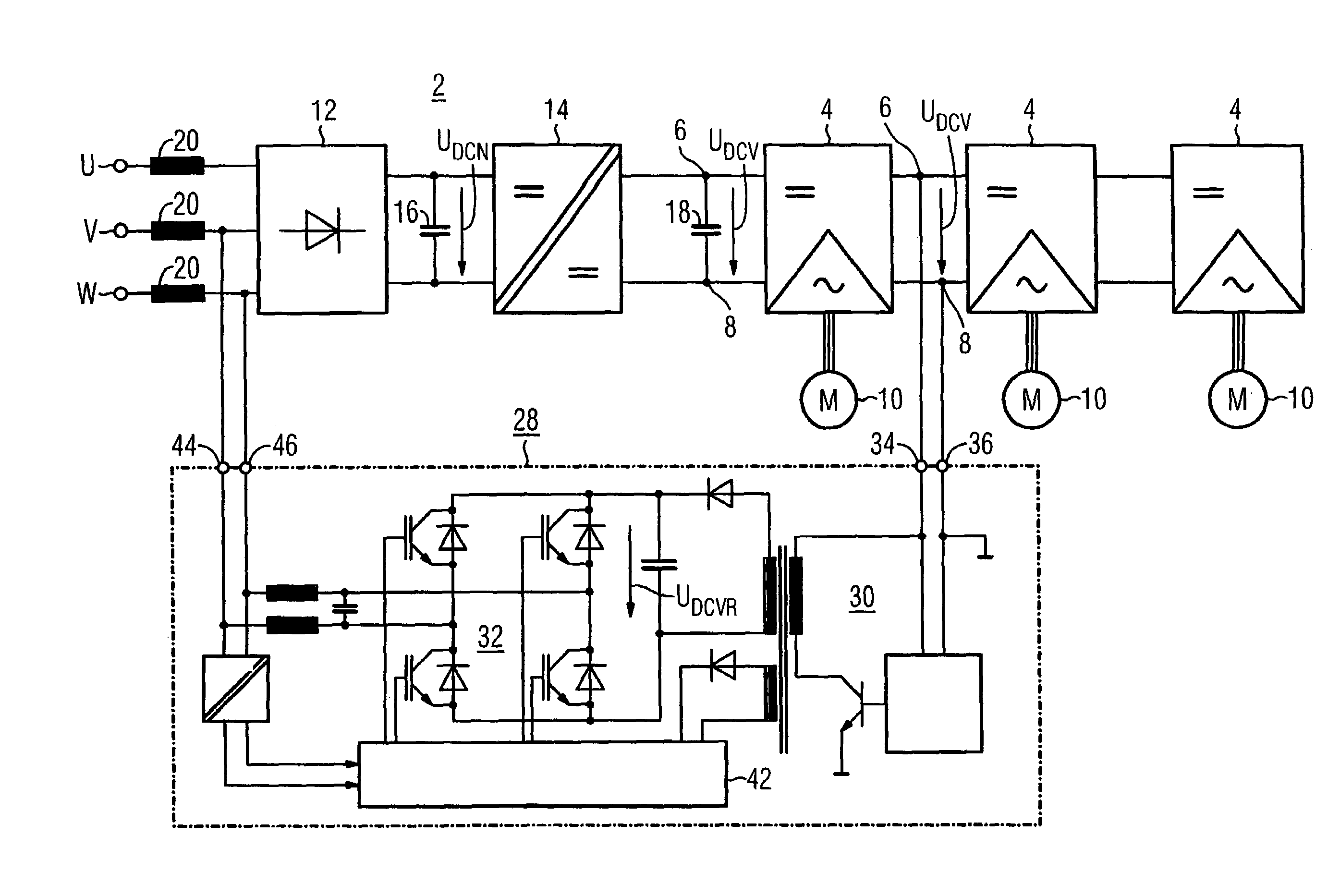
[0027]Turning now to the drawing, and in particular to FIG. 3, there is shown an energy recovery device 28 according to the invention, which has as an input a DC / DC converter 30 and as an output a line-commutated bidirectional rectifier 32, with an output of the DC / DC converter 30 being connected to the DC input side of the bidirectional rectifier 32. The DC supply voltage UDCV of the inverters 4 is applied to the input terminals 34 and 36 of the energy recovery device 28, whereas a voltage UDCVR, which is also referred to as energy recovery voltage and has an amplitude that is greater than an equivalent DC value of the line voltage of a supply grid, is applied to the output terminals 38 and 40 of the DC / DC converter 30. Since the line-commutated bidirectional rectifier 32 of the energy recovery device 28 conducts current in both directions, the voltage drop between the energy recovery voltage UDCVR and the DC-equivalent value of the line voltage can cause current to flow through th...

second embodiment

[0034]FIG. 6 shows a drive system of the invention, whereby the line-commutated converter 12 is configured for bidirectional current flow. As schematically shown in FIG. 6, electronically controllable switches are connected electrically in parallel with each diode of this converter, with the switches switched to a conducting state only during the conducting phases of the diodes, thereby allowing bidirectional current flow. This embodiment of the bidirectional rectifier 12 therefore corresponds to the line-commutated bidirectional rectifier 32 of the energy recovery device 28 of FIG. 3. Because the line-side converter 12 of the central power supply 2 of the drive system is then always capable of energy recovery, the converter 32 shown in FIG. 3 can be omitted from the energy recovery device 28, so that only the DC / DC converter 30 remains in this embodiment of the energy recovery device 28. Moreover, the output of this embodiment of the energy recovery device 28 is also no longer conn...


PUM


Abstract

A drive system includes a central power supply with a line-commutated converter and a DC / DC converter connected downstream of the line-commutated converter, and a plurality of inverters, each inverter having an output connected a load, for example a motor, and a DC input connected to a regulated DC voltage output of the central power supply. Buffer capacitors are connected across the respective input and output of the DC / DC converter. The drive system further includes an energy recovery device with an input connected to the controlled voltage output of the central power supply and an output connected to at least two input terminals of the line-commutated converter. This type of drive system eliminates a bulky brake circuit.

Description

CROSS-REFERENCES TO RELATED APPLICATIONS[0001]This application claims the priority of German Patent Application, Serial No. 103 56 515.9, filed Dec. 3, 2003, pursuant to 35 U.S.C. 119(a)–(d).BACKGROUND OF THE INVENTION[0002]The present invention relates to a drive system for electric motors, and more particularly to a drive system that allows energy recovery from a plurality of electric motors during a braking operation.[0003]Nothing in the following discussion of the state of the art is to be construed as an admission of prior art.[0004]A drive system of this type is illustrated in FIG. 1 and includes a central power supply 2 having a line-commutated converter 12 and a DC / DC converter 14, as well as a plurality of inverters 4. A DC-input of each of the inverters 4 is connected to an output of the DC / DC converter 14, whereas the respective AC outputs of the inverters 4 are connected to corresponding multi-phase electric motors 10. The input of the line-commutated converter 12 is con...

Claims


Application Information

Patent Timeline
Patent Type & Authority Patents(United States)
IPC IPC(8): H02P27/04H02P27/00H02M7/81H02P3/18H02P5/747H02P23/06
CPCH02P5/747H02P23/065B60L9/22B60L15/007Y02T10/7216B60L2240/36Y02T10/645Y02T10/644B60L2210/10H02P23/07Y02T10/64Y02T10/72
Inventor ECKARDT, DIETER
Owner SIEMENS AG
Why Eureka
Try Eureka