
Detection of color filter array alignment in image sensors

a color filter array and image sensor technology, applied in the field of image sensors, can solve the problems of severe color distortion, misalignment of cfa relative, etc., and achieve the effects of reducing per unit manufacturing cost, cost effective, and increasing manufacturing yields

Active Publication Date: 2006-04-11
PIXIM
View PDF8 Cites 28 Cited by
  • Summary
  • Abstract
  • Description
  • Claims
  • Application Information

AI Technical Summary

Benefits of technology

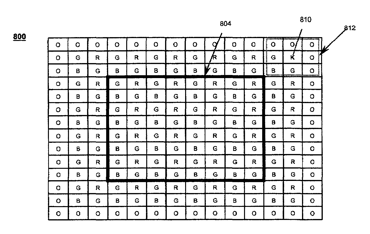
[0011]The present invention provides methods for detecting and compensating for misalignments of one or more rows and / or columns between a color filter array (CFA) and a sensor array that may occur during the color sensor array (CSA) fabrication process. These methods are very cost effective and enable the use of image sensors with misaligned CFAs just as if they were manufactured correctly. The present invention also enables the use of CSAs in which the alignment of a CFA relative to the corresponding sensor array is unknown. The benefits of the present invention include (1) increased manufacturing yields and, therefore, lower per unit manufacturing cost and (2) higher reliability of image sensors having CFAs.

Problems solved by technology

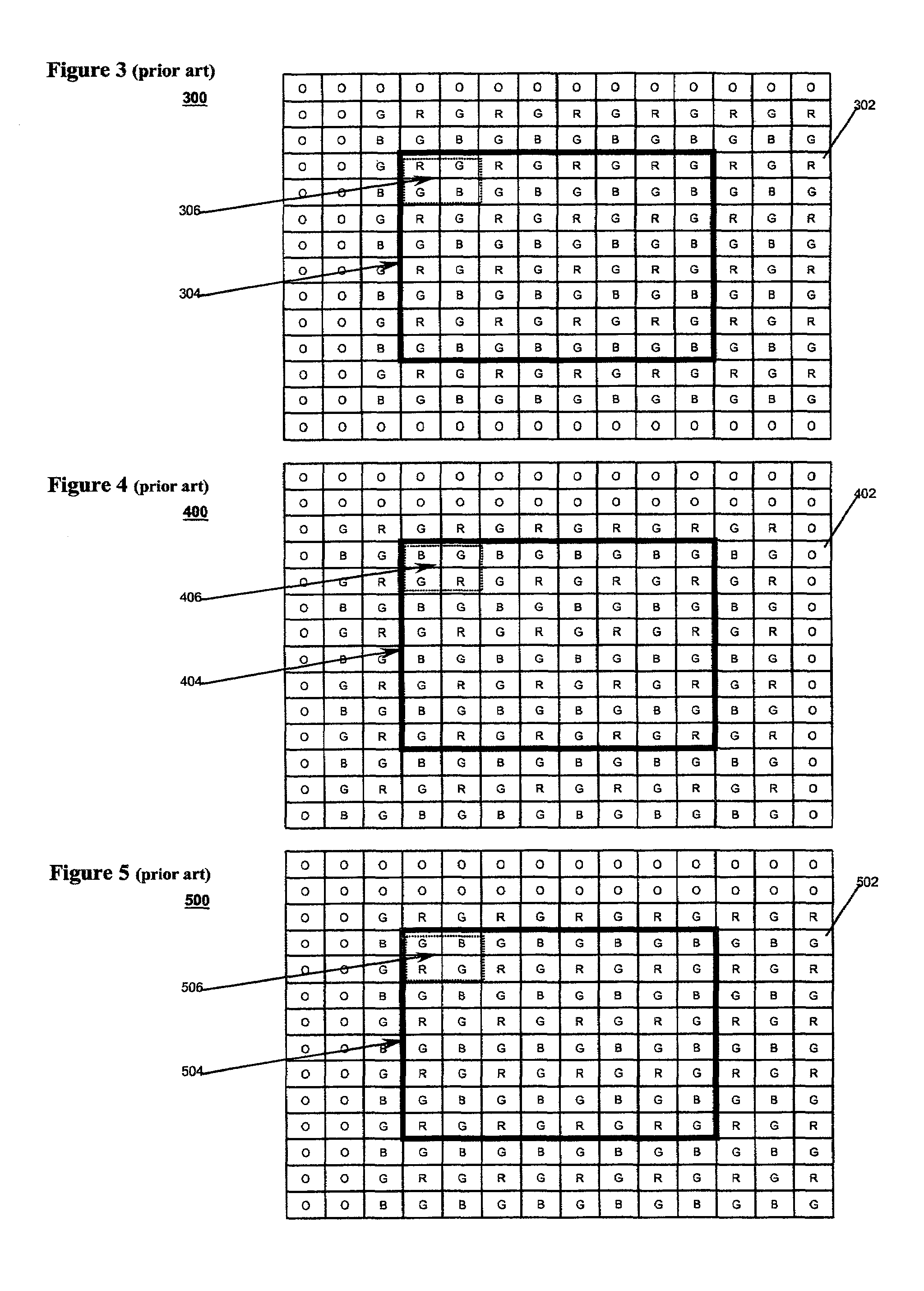
A common manufacturing defect is misalignment of the CFA relative to the sensor array.
If a digital image is produced using CSA 300, severe color distortion may result.

Method used


Image

  • Detection of color filter array alignment in image sensors
  • Detection of color filter array alignment in image sensors
  • Detection of color filter array alignment in image sensors

Examples


Embodiment Construction

[0023]Reference herein to “one embodiment” or “an embodiment” means that a particular feature, structure, or characteristic described in connection with the embodiment can be included in at least one embodiment of the invention. The appearances of the phrase “in one embodiment” in various places in the specification are not necessarily all referring to the same embodiment, nor are separate or alternative embodiments mutually exclusive of other embodiments. The description herein is largely based on a particular image sensor having a digital sensor array configured with a Bayer color filter array. Those skilled in the art can appreciate that the description can be equally applied to other image sensors including analog sensor arrays and other color filter arrays.

[0024]FIG. 6 is a flowchart showing an off-line method 600 of detecting and compensating for manufacturing defects of the types illustrated in FIGS. 3–5 according to one embodiment of the present invention. In a first step 60...


PUM


Abstract

Methods of detecting relative misalignment between a color filter array and a sensor array in a color sensor array. The present invention provides methods for detecting and compensating for shifts of one or more rows and / or columns between a color filter array and a sensor array that may occur during the color sensor array fabrication process. The present invention also enables the use of color sensor arrays in which the alignment of a color filter array relative to the corresponding sensor array is unknown. In one embodiment, a detectable pattern of one or more pixels (e.g., pixels having black filters) is introduced into the periphery of the color sensor array. The position of the pattern is detected and color image data are processed with respect to the detected position. The invention is very cost effective and enables the use of image sensors with misaligned color filter arrays just as if they were manufactured correctly. The benefits of the present invention include (1) increased manufacturing yields and, therefore, lower per unit manufacturing cost and (2) higher reliability of image sensors configured with color filter arrays.

Description

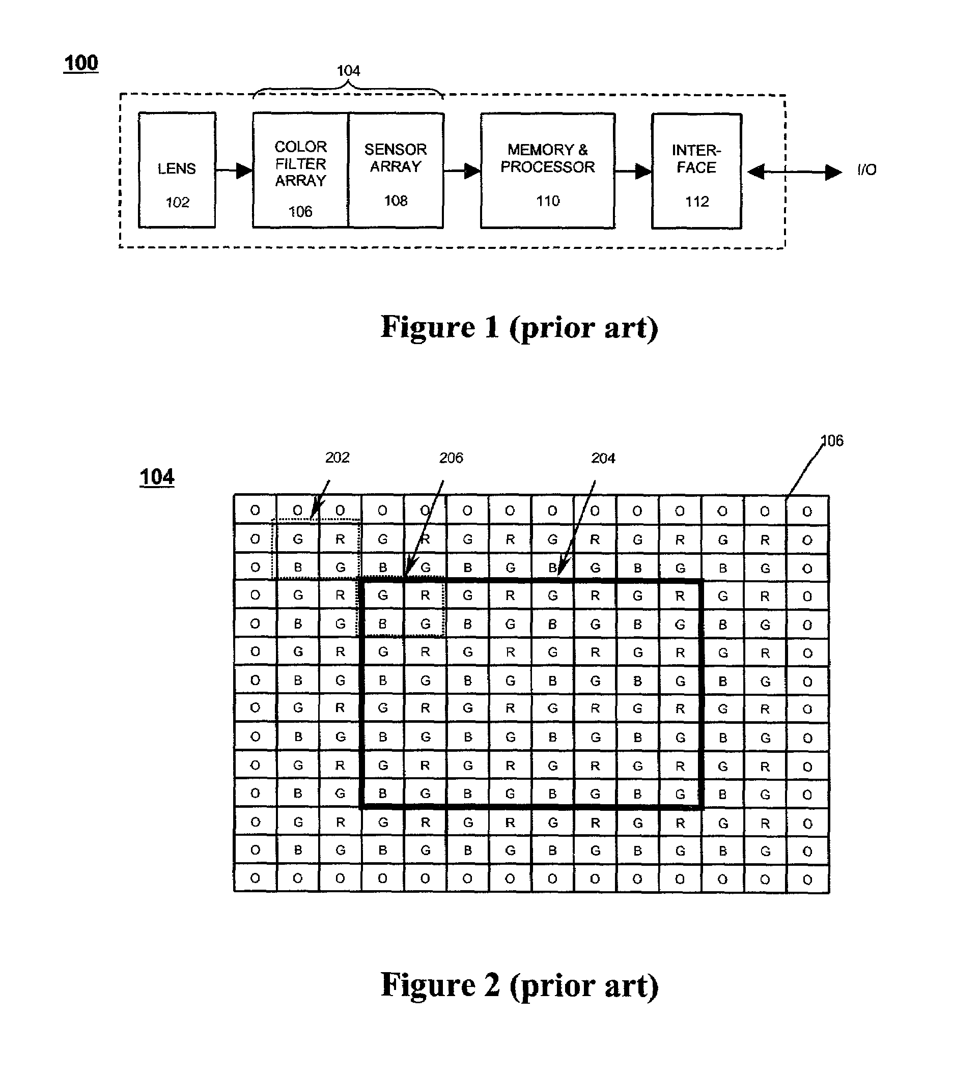
BACKGROUND OF THE INVENTION[0001]1. Field of the Invention[0002]The present invention relates to image sensors configured with color filter arrays.[0003]2. Description of the Related Art[0004]Imaging systems, such as digital cameras, are used for still photography and video recording. The images captured by the system may be used for viewing / processing in a variety of representations, such as electronic, digital, or printed. For color imaging, image data are typically captured in three different colors, e.g., red, green, and blue. When the three sets of data representing the colors are combined, a color image of the scene is created. Capturing these three sets of data can be achieved in a number of ways. In digital imaging, this is often accomplished by using a two-dimensional sensor array comprising photosensitive pixels that are covered by a pattern of red, green, and blue filters, which pattern is known as a color filter array (CFA).[0005]FIG. 1 shows a schematic block diagram of...

Claims


Application Information

Patent Timeline
Patent Type & Authority Patents(United States)
IPC IPC(8): H04N9/47
CPCH04N5/3572H04N9/093H04N9/045H04N23/84H04N25/134
Inventor REYNERI, JUSTINMOTTA, RICARDO J.
Owner PIXIM
Learn More