
Apparatus for look-ahead thermal sensing in a data storage device

Inactive Publication Date: 2006-04-11
WESTERN DIGITAL TECH INC
View PDF15 Cites 27 Cited by
  • Summary
  • Abstract
  • Description
  • Claims
  • Application Information

AI Technical Summary

Benefits of technology

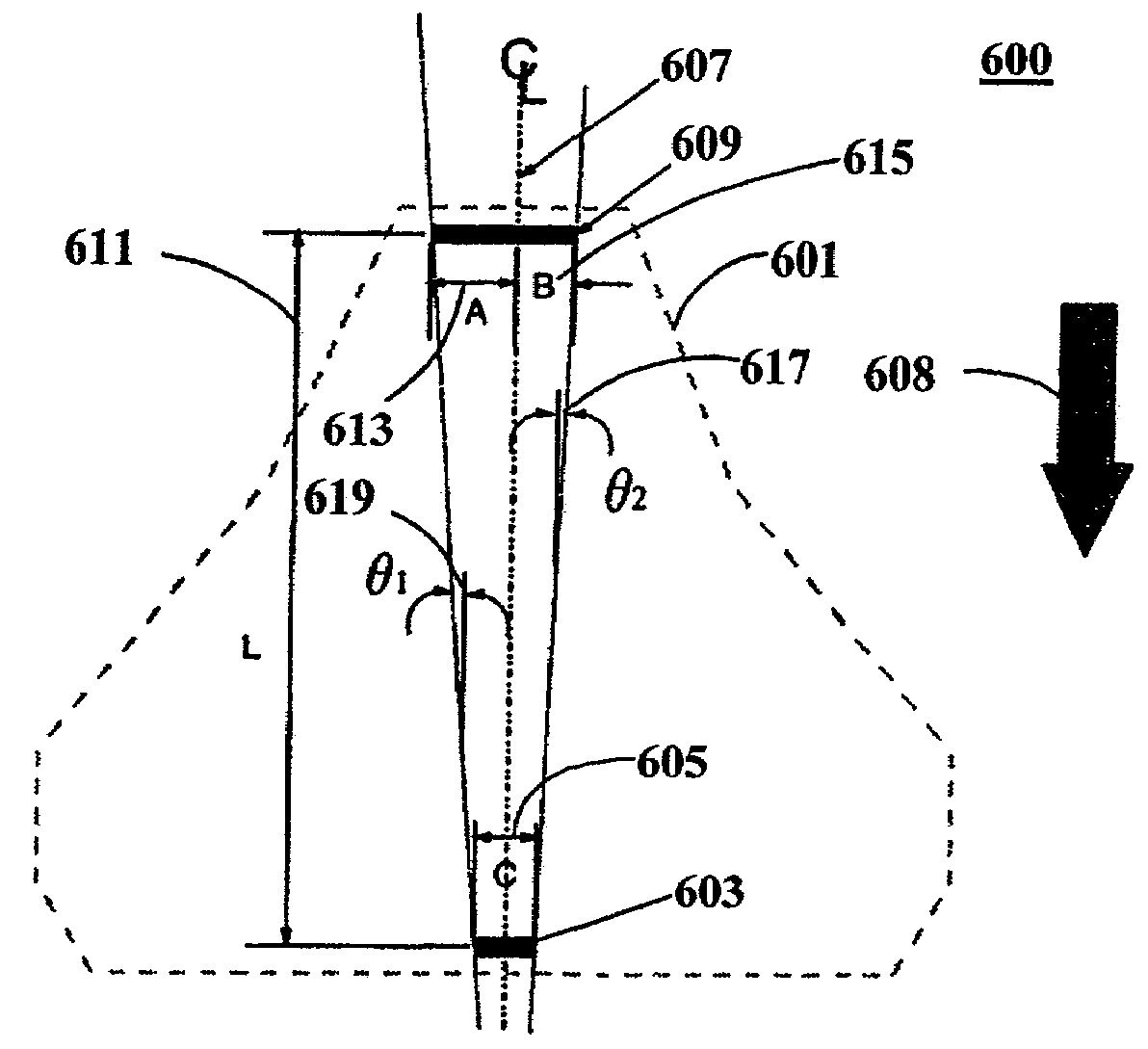
[0017]In accordance with a first aspect of the present invention, there is provided a slider assembly having a slider with leading and trailing edges configured to fly on an airbearing above a data storage disk rotating from the leading edge to the trailing edge. Read and write heads are mounted on the slider proximate the trailing edge. An auxiliary thermal sensor is mounted on the slider, but preferably nearer the leading edge. Forward placement of the auxiliary thermal sensor allows it to sense mechanical defects before they reach the heads, thereby permitting a write inhibit operation, for example. The auxiliary thermal sensor may also be used to detect airbearing modulation. Appropriate action may be taken when unacceptable airbearing modulation is detected, such as notifying the user and / or scrubbing the slider. The auxiliary thermal sensor is preferably wider than the heads. This allows, for example, an in-situ glide test to be performed faster using the auxiliary thermal sensor.
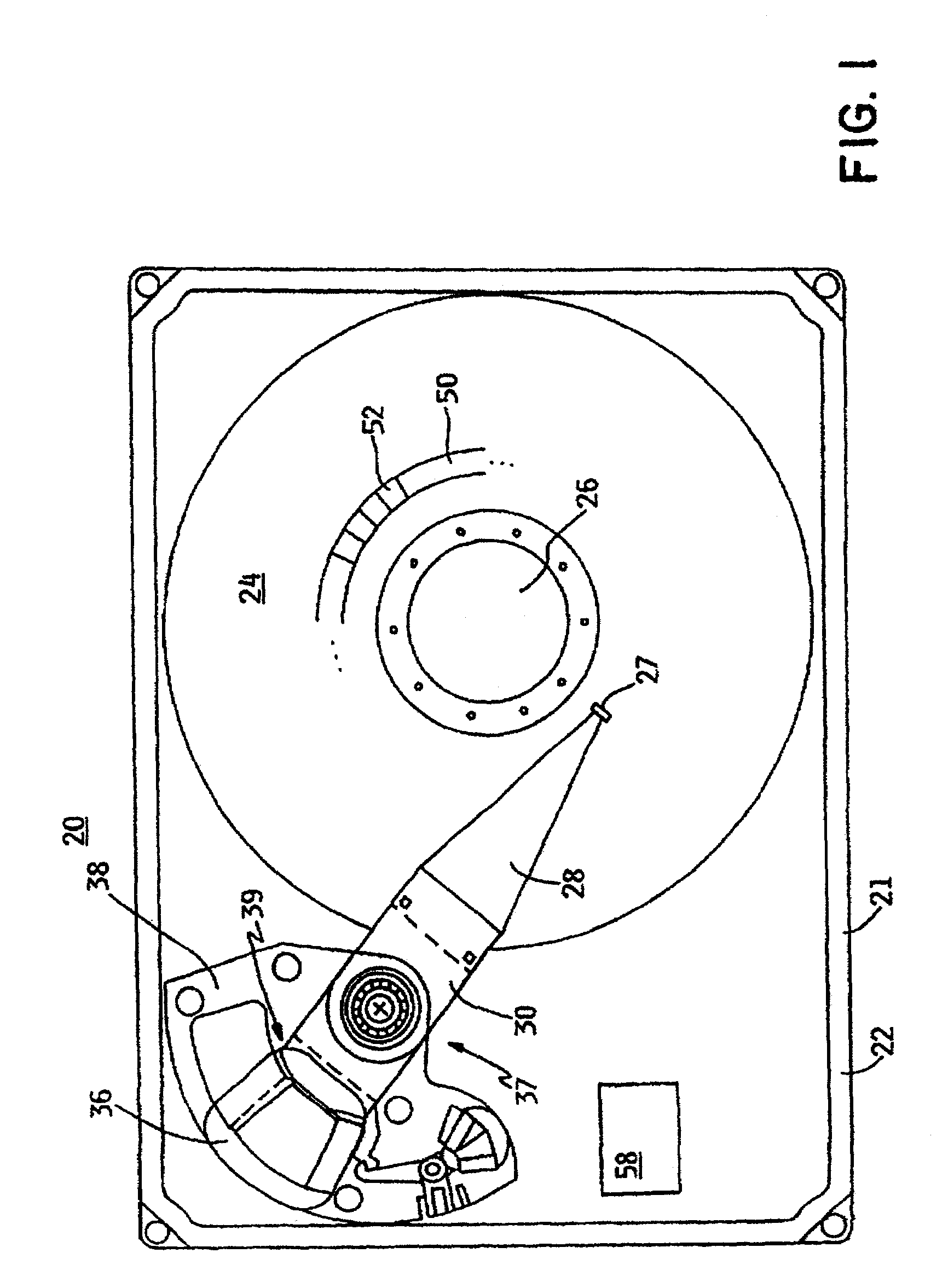
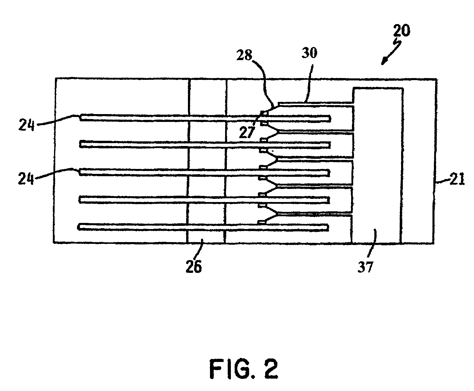
[0018]In accordance with a second aspect of the present invention, there is provided a data storage device having a data storage disk, a slider, an actuator provided to position the slider relative to the storage disk, and a motor provided to rotate the storage disk relative to the slider. The slider has leading and trailing edges configured to fly on an airbearing above the data storage disk rotating from the leading edge to the trailing edge. Read and write heads are mounted on the slider proximate the trailing edge. An auxiliary thermal sensor is mounted on the slider, but preferably nearer the leading edge. Forward placement of the auxiliary thermal sensor allows it to sense mechanical defects before they reach the heads, thereby permitting a write inhibit operation, for example. The auxiliary thermal sensor may also be used to detect airbearing modulation. Appropriate action may be taken when unacceptable airbearing modulation is detected, such as notifying the user and / or scrubbing the slider. The auxiliary thermal sensor is preferably wider than the heads. This allows, for example, an in-situ glide test to be performed faster using the auxiliary thermal sensor.

Problems solved by technology

Appropriate action may be taken when unacceptable airbearing modulation is detected, such as notifying the user and / or scrubbing the slider.

Method used


Image

  • Apparatus for look-ahead thermal sensing in a data storage device
  • Apparatus for look-ahead thermal sensing in a data storage device
  • Apparatus for look-ahead thermal sensing in a data storage device

Examples


Embodiment Construction

[0032]The present invention addresses the problem of detecting slider dynamics and disk defects by using an auxiliary thermal sensor attached to an airbearing slider in a disk drive. More specifically, the present invention uses a auxiliary thermal sensor that is similar to conventional magnetoresistive (MR) and giant magnetoresistance (GMR) heads, but is located some distance away from the usual placement of these heads. The auxiliary thermal sensor is preferably located forward (i.e., toward the leading edge) of the slider airbearing. In addition, the width of the auxiliary thermal sensor is preferably much greater, in a track width direction, than that of conventional MR and GMR heads. Furthermore, the sensitivity of the auxiliary thermal sensor to changes in the slider-to-disk spacing can be made many times that of conventional MR and GMR heads. Also, the auxiliary thermal sensor is preferably constructed so that the magnetic fields emanating from it are minimized so as not to i...


PUM

PropertyMeasurementUnit
separation distanceaaaaaaaaaa
temperatureaaaaaaaaaa

Abstract

A slider having leading and trailing edges is configured to fly on an airbearing above a data storage disk rotating from the leading edge to the trailing edge. Read and write heads are mounted on the slider proximate the trailing edge. An auxiliary thermal sensor is mounted on the slider, but preferably nearer the leading edge. Forward placement of the sensor allows it to sense mechanical defects before they reach the heads, thereby permitting a write inhibit operation, for example. The sensor may also be used to detect airbearing modulation. Appropriate action may be taken when unacceptable airbearing modulation is detected, such as notifying the user and / or scrubbing the slider. The sensor is preferably wider than the heads. This allows, for example, an in-situ glide test to be performed faster using the sensor. An arm electronics module is preferably configured to permit concurrent operation of the sensor and heads.

Description

CROSS-REFERENCE TO RELATED APPLICATION[0001]This patent application is related to 10 / 140,699, filed concurrently, entitled “METHOD FOR LOOK-AHEAD THERMAL SENSING IN A DATA STORAGE DEVICE”, which is assigned to the assignee of the instant application.FIELD OF THE INVENTION[0002]The present invention relates in general to data storage systems. In particular, the present invention relates to apparatus for look-ahead thermal sensing in a data storage device.BACKGROUND[0003]A typical magnetic data storage system includes a magnetic medium for storing data in magnetic form and a transducer used to write and read magnetic data respectively to and from the medium. A disk storage device, for example, includes one or more data storage disks coaxially mounted on a hub of a spindle motor. The spindle motor rotates the disks at speeds typically on the order of several thousand revolutions-per-minute. Digital information, representing various types of data, is typically written to and read from t...

Claims


Application Information

Patent Timeline
Patent Type & Authority Patents(United States)
IPC IPC(8): G11B5/02G11B5/10G11B5/31G11B5/39G11B5/455G11B5/48G11B5/60G11B27/36
CPCG11B5/10G11B5/6005G11B27/36G11B5/3103G11B5/3945G11B5/455G11B2220/20G11B5/4886G11B5/488
Inventor OTTESEN, HAL HJALMARSMITH, GORDON JAMESSRI-JAYANTHA, SRI M.
Owner WESTERN DIGITAL TECH INC
Learn More