
High voltage tolerant electrostatic discharge (ESD) protection clamp circuitry

a protection circuitry and high voltage technology, applied in the direction of emergency protection arrangements for limiting excess voltage/current, electrical equipment, semiconductor devices, etc., can solve the problems of increasing the power requirements of such systems, and the problem of providing esd protection circuitry which is tolerant of higher operating voltages, e.g., 40–60 volts, is more problemati

Active Publication Date: 2006-04-11
NAT SEMICON CORP
View PDF9 Cites 21 Cited by
  • Summary
  • Abstract
  • Description
  • Claims
  • Application Information

AI Technical Summary

Benefits of technology

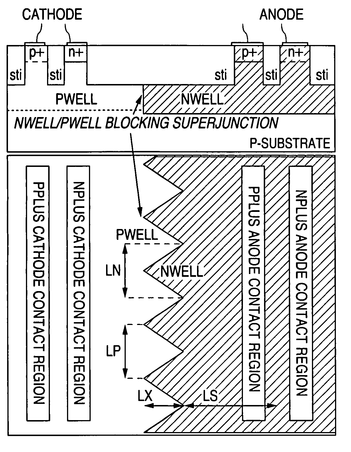
[0007]In accordance with the presently claimed invention, high voltage tolerant electrostatic discharge (ESD) protection clamp circuitry includes a self-triggering device having a blocking junction with a two-dimensional geometrical lateral profile.
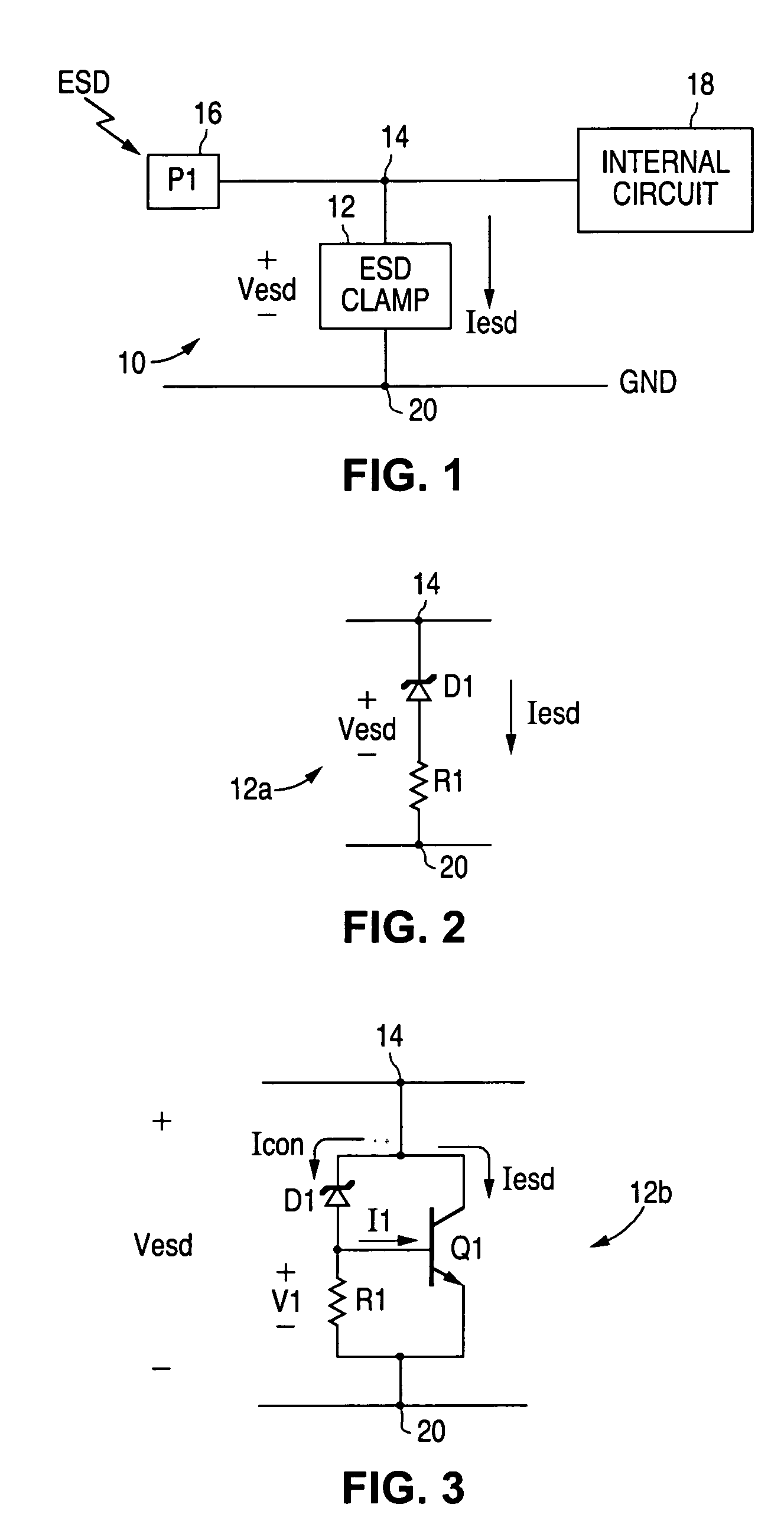
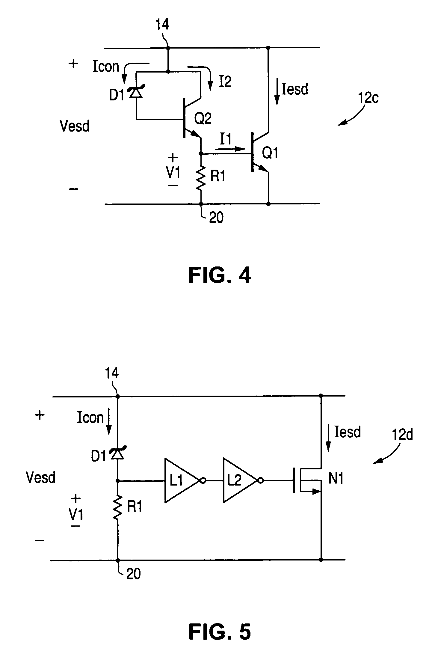
[0008]In accordance with one embodiment of the presently claimed invention, high voltage tolerant electrostatic discharge (ESD) protection clamp circuitry includes a first terminal to convey desired and undesired signals, a second terminal and self-triggering current shunting circuitry. The self-triggering current shunting circuitry is coupled between the first and second terminals, provides a conductive current path between the first and second terminals in response to the undesired signal while providing a nonconductive current path otherwise, and includes a self-triggering device having a blocking junction with a two-dimensional geometrical lateral profile.
[0009]In accordance with another embodiment of the presently claimed invention, high voltage tolerant electrostatic discharge (ESD) protection clamp circuitry includes a first terminal to convey desired and undesired signals, a second terminal, current shunting circuitry and self-triggering circuitry. The current shunting circuitry is coupled between the first and second terminals, and responsive to a control current having first and second states, wherein during the first and second control current states the current shunting circuitry provides nonconductive and conductive current paths, respectively, between the first and second terminals. The self-triggering circuitry is coupled to the first terminal and the current shunting circuitry, includes a self-triggering device having a blocking junction with a two-dimensional geometrical lateral

Problems solved by technology

As automobiles incorporate increasingly complex and sophisticated electronic systems, power requirements for such systems increase significantly.
However, providing ESD protection circuitry which is tolerant of the higher operating voltages, e.g., 40–60 volts, has been more problematic.

Method used


Image

  • High voltage tolerant electrostatic discharge (ESD) protection clamp circuitry
  • High voltage tolerant electrostatic discharge (ESD) protection clamp circuitry
  • High voltage tolerant electrostatic discharge (ESD) protection clamp circuitry

Examples


Embodiment Construction

[0017]The following detailed description is of example embodiments of the presently claimed invention with references to the accompanying drawings. Such description is intended to be illustrative and not limiting with respect to the scope of the present invention. Such embodiments are described in sufficient detail to enable one of ordinary skill in the art to practice the subject invention, and it will be understood that other embodiments may be practiced with some variations without departing from the spirit or scope of the subject invention.

[0018]Throughout the present disclosure, absent a clear indication to the contrary from the context, it will be understood that individual circuit elements as described may be singular or plural in number. For example, the terms “circuit” and “circuitry” may include either a single component or a plurality of components, which are either active and / or passive and are connected or otherwise coupled together (e.g., as one or more integrated circ...


PUM


Abstract

High voltage tolerant electrostatic discharge (ESD) protection clamp circuitry including a self-triggering device having a blocking junction with a two-dimensional geometrical lateral profile.

Description

BACKGROUND OF THE INVENTION[0001]1. Field of the Invention[0002]The present invention relates to electrostatic discharge (ESD) protection circuitry, and in particular, to ESD protection circuitry tolerant of high operating voltages and signals.[0003]2. Description of the Related Art[0004]As is well known, a recent trend in the design of products employing significant analog circuitry includes the combining of many if not all functional blocks of analog circuitry within a single integrated circuit (IC), or “chip”. Ideally, such an analog chip must be compatible with, or at least tolerant of, the voltage levels of the input and output signals, as well as the power supply for the system. Indeed, some chips must be able to provide a power supply for the output device (e.g., as is the case for many new universal serial bus, or “USB”, devices) or to charge batteries during a data exchange.[0005]One example of such a new product environment is the rapidly growing market of automotive appli...

Claims


Application Information

Patent Timeline
IPC IPC(8): H02H9/00
CPCH01L27/0251H01L29/7436H01L29/0692H01L29/0688H01L29/0634
Inventor VASHCHENKO, VLADISLAVHOPPER, PETER J.
Owner NAT SEMICON CORP
Learn More