Low cost thermal management device or heat sink manufactured from conductive loaded resin-based materials

a technology of thermal management device and heat sink, which is applied in the direction of conductive pattern formation, emergency protective arrangement for automatic disconnection, metal pattern materials, etc., can solve the problems of large heat loss, large heat loss of high current switches, and many thermal management problems of modern electronic systems, and achieve effective heat dissipation

Inactive Publication Date: 2006-04-11
INTEGRAL TECHNOLOGY INC
View PDF39 Cites 30 Cited by
  • Summary
  • Abstract
  • Description
  • Claims
  • Application Information

AI Technical Summary

Benefits of technology

[0011]A principal object of the present invention is to provide an effective heat dissipation device.
[0012]A further object of the present invention is to provide a method to form a heat dissipation device.
[0013]A further object of the present invention is to provide a heat sink or heat pipe molded of conductive loaded resin-based materials.
[0014]A yet further object of the present invention is to provide a heat sink or heat pipe molded of conductive loaded resin-based materials where the thermal characteristics of the heat sink or heat pipe can be adjusted by altering the composition of the conductive loaded resin-based materials.
[0015]A yet further object of the present invention is to provide a heat sink or heat pipe molded of conductive loaded resin-based material where the thermal characteristics can be altered or the visual characteristics can be altered by forming a metal layer over the conductive loaded resin-based material.
[0017]A yet further object of the present invention is to provide a method to fabricate a heat sink or heat pipe from a conductive loaded resin-based material where the material is in the form of a fabric.

Problems solved by technology

Modern electronic systems create many thermal management problems.
For example, integrated circuits operating at very high switching speeds generate a large amount of heat due to IR losses.
In addition, high current switches generate a large amount of heat loss due to IR that must be dissipated from the device to avoid a failure.
Further, the heat sink dissipates this thermal energy at a rate sufficient to maintain thermal energy flow from the heat-producing device into the heat sink.
Among these disadvantages are the material and manufacturing cost of metal, especially copper, and the weight of the metal.

Method used


Image

  • Low cost thermal management device or heat sink manufactured from conductive loaded resin-based materials
  • Low cost thermal management device or heat sink manufactured from conductive loaded resin-based materials
  • Low cost thermal management device or heat sink manufactured from conductive loaded resin-based materials

Examples


Embodiment Construction

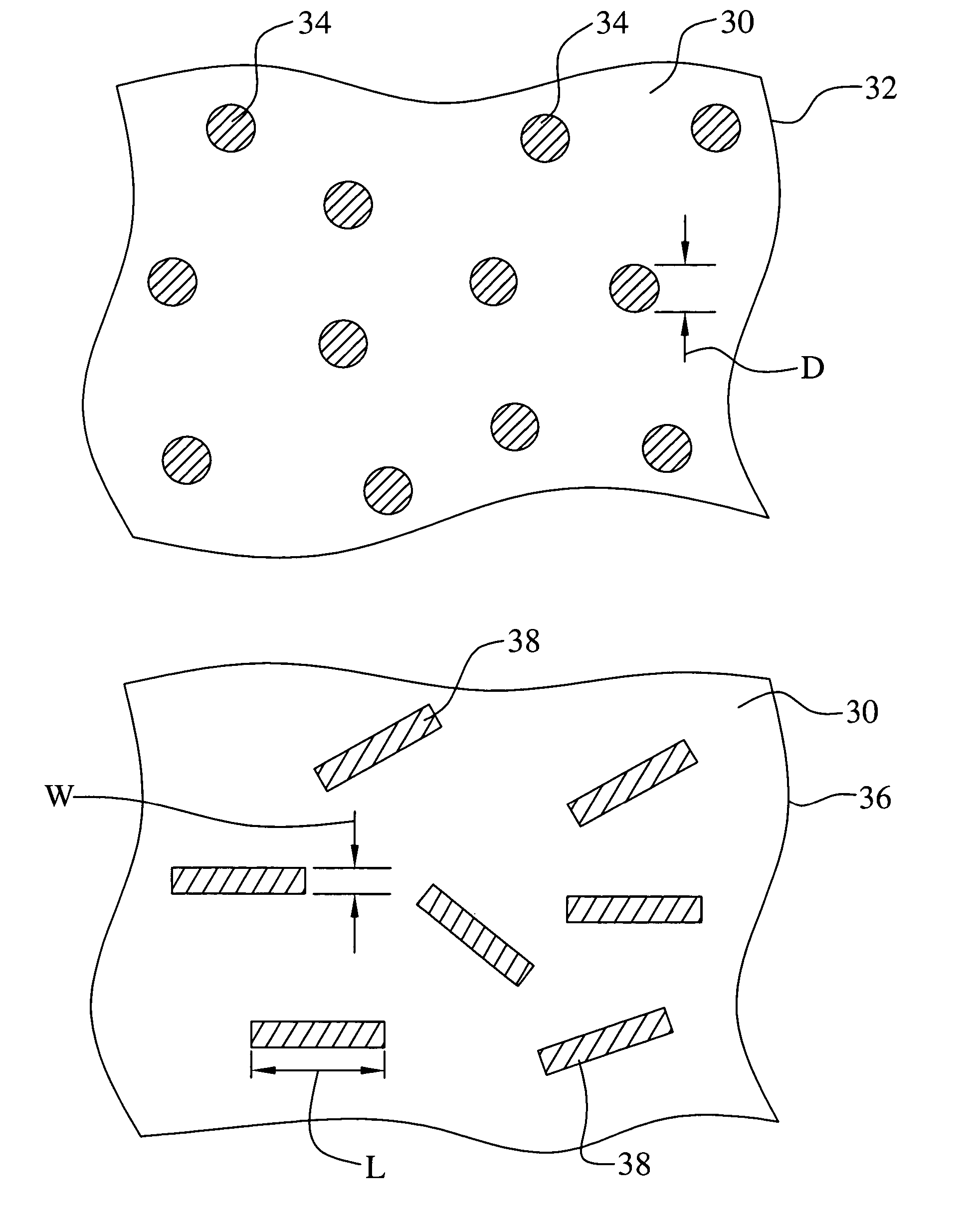
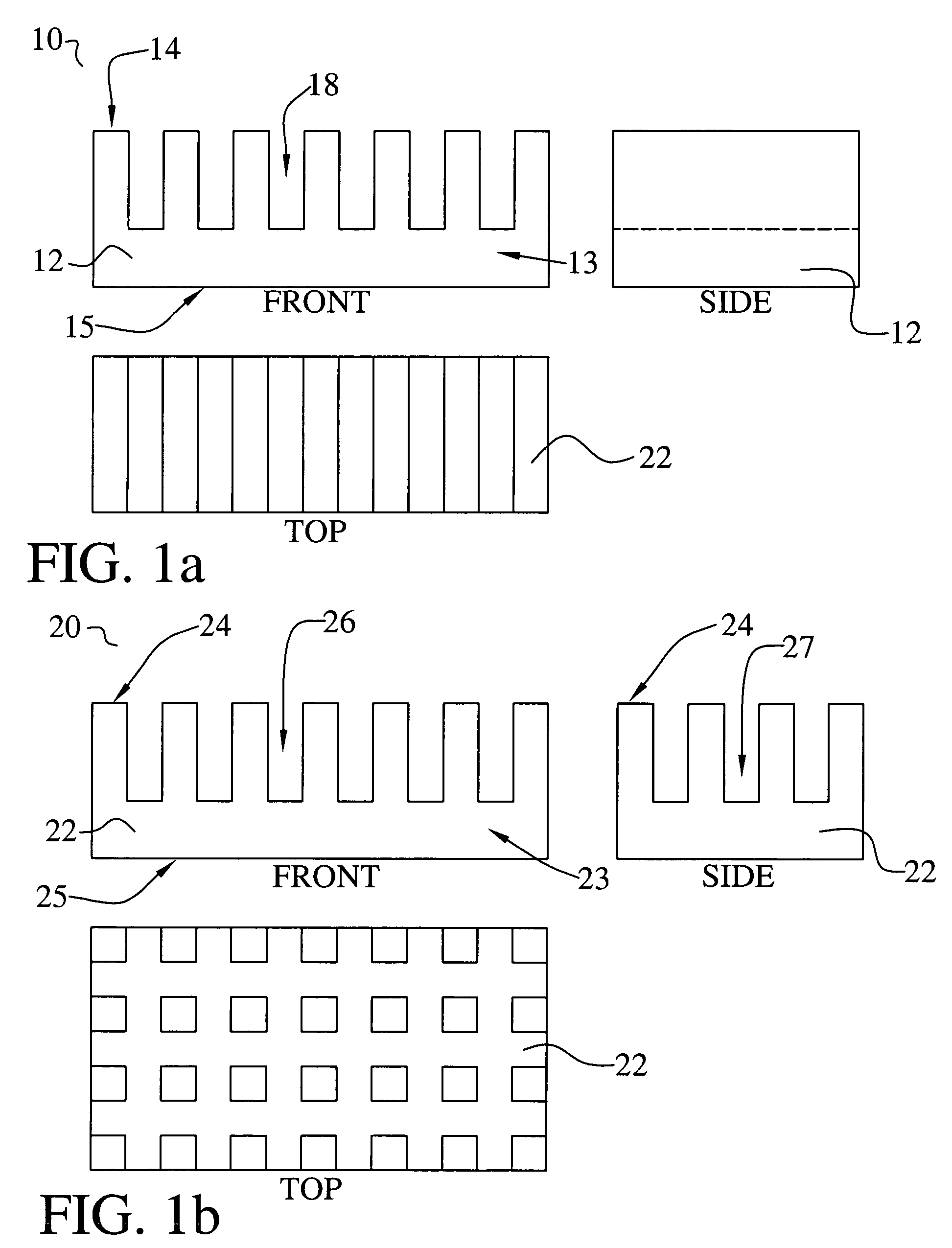
[0036]This invention relates to heat sinks and to other thermal management devices molded of conductive loaded resin-based materials comprising micron conductive powders, micron conductive fibers, or a combination thereof, homogenized within a base resin when molded.

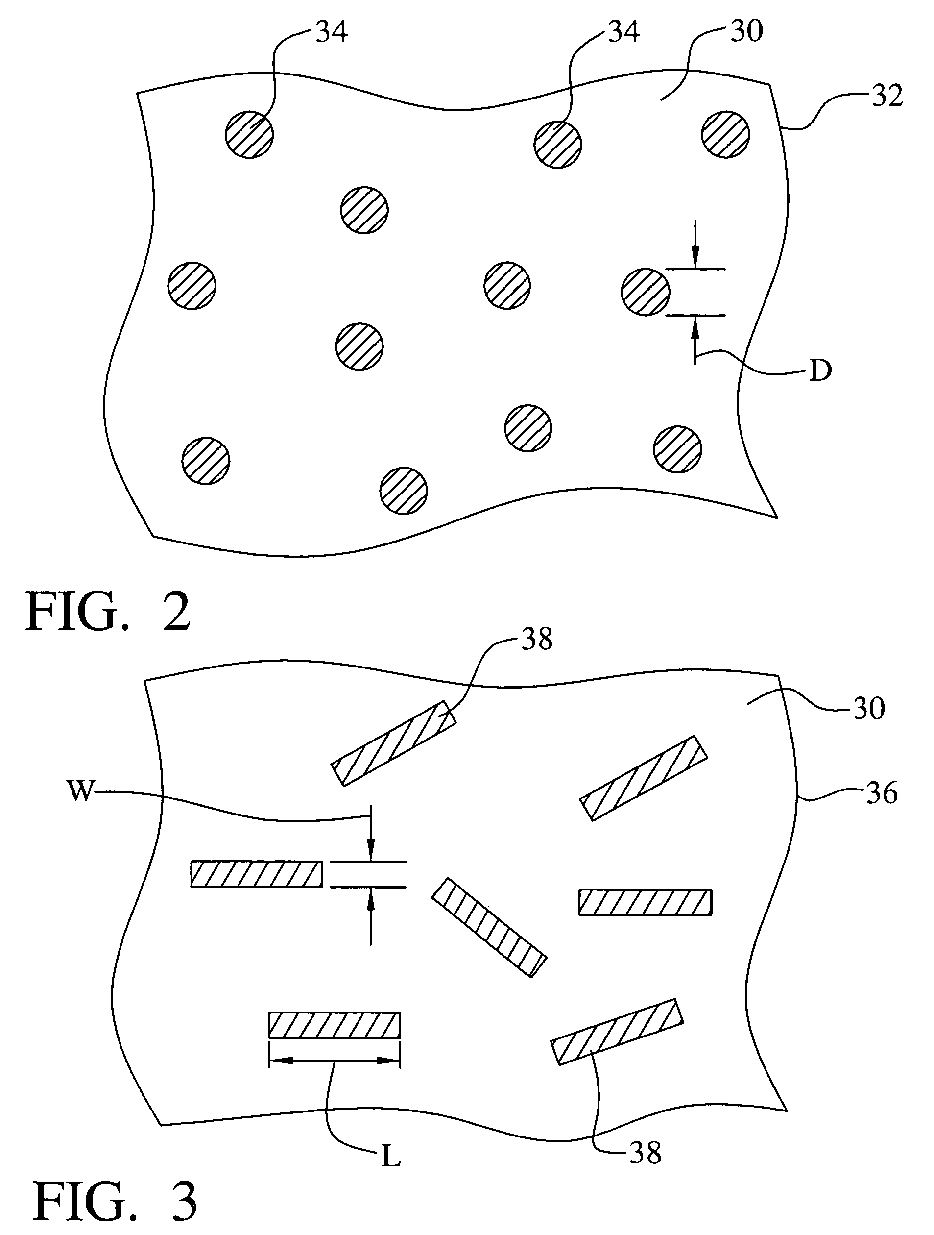
[0037]The conductive loaded resin-based materials of the invention are base resins loaded with conductive materials, which then makes any base resin a conductor rather than an insulator. The resins provide the structural integrity to the molded part. The micron conductive fibers, micron conductive powders, or a combination thereof, are homogenized within the resin during the molding process, providing the electrical continuity.

[0038]The conductive loaded resin-based materials can be molded, extruded or the like to provide almost any desired shape or size. The molded conductive loaded resin-based materials can also be cut, stamped, or vacuumed formed from an injection molded or extruded sheet or bar stock, over-molded, la...


PUM

PropertyMeasurementUnit
diameteraaaaaaaaaa
diameteraaaaaaaaaa
lengthaaaaaaaaaa

Abstract

Heat sinks, heat pipes, and other thermal management devices are formed of a conductive loaded resin-based material. The conductive loaded resin-based material comprises micron conductive powder(s), conductive fiber(s), or a combination of conductive powder and conductive fibers in a base resin host. The ratio of the weight of the conductive powder(s), conductive fiber(s), or a combination of conductive powder and conductive fibers to the weight of the base resin host is between about 0.20 and 0.40. The micron conductive powders are formed from non-metals, such as carbon, graphite, that may also be metallic plated, or the like, or from metals such as stainless steel, nickel, copper, silver, that may also be metallic plated, or the like, or from a combination of non-metal, plated, or in combination with, metal powders. The micron conductor fibers preferably are of nickel plated carbon fiber, stainless steel fiber, copper fiber, silver fiber, or the like.

Description

[0001]This Patent Application claims priority to the U.S. Provisional Patent Application 60 / 462,072, filed on Apr. 14, 2003 and to the U.S. Provisional Patent Application 60 / 478,775, filed on Jun. 16, 2003 which are herein incorporatod by reference in their entirety.[0002]This Patent Application is a Continuation-in-Part of INT01-002CIP, filed as U.S. patent application Ser. No. 10 / 309,429, filed on Dec. 4, 2002, now issued as U.S. Pat. No. 6,870,516, also incorporated by reference in its entirety, which is a Continuation-in-Part application of docket number INT01-002, filed as U.S. patent application Ser. No. 10 / 075,778, filed on Feb. 14, 2002, now issued as U.S. Pat. No. 6,741,221, which claimed priority to U.S. Provisional Patent Applications Ser. No. 60 / 317,808, filed on Sep. 7, 2001, Ser. No. 60 / 269,414, filed on Feb. 16, 2001, and Ser. No. 60 / 268,822, filed on Feb. 15, 2001.BACKGROUND OF THE INVENTION[0003](1) Field of the Invention[0004]This invention relates to thermal manag...

Claims


Application Information

Patent Timeline
Patent Type & Authority Patents(United States)
IPC IPC(8): H05K7/20F28D15/02B29C45/00F21V29/00G06K19/077H01L21/48H01L23/373H01L23/427H01Q1/12H01Q1/24H01Q1/32H01Q1/36H01Q1/38H01Q1/40H01Q9/04H01Q9/16H01Q9/30H01Q21/00H05K1/09H05K3/10
CPCF21V29/76F28D15/04F28F21/062G06K19/07749H01L21/4878H01L23/3737H01L23/427H05K3/101B29C45/0013F21V29/677B29C45/0001B29K2995/0005B29L2031/3456F21V29/004F21Y2101/02F28F3/048F28F21/067H01H2203/0085H05K1/095H05K3/107H05K2201/0281H05K2201/09118H05K2203/0113H01L2924/0002H01L2924/00F28F2215/04F21V29/89F21Y2115/10G01B13/06
Inventor AISENBREY, THOMAS
Owner INTEGRAL TECHNOLOGY INC
Why Eureka
Try Eureka