
Time domain passivity control of haptic interfaces

Inactive Publication Date: 2006-04-11
UNIV OF WASHINGTON
View PDF16 Cites 24 Cited by
  • Summary
  • Abstract
  • Description
  • Claims
  • Application Information

AI Technical Summary

Benefits of technology

[0015]The term “stabilizing” means to reduce or minimize the sense of “vibration” or bounce when the user encounters a virtual object, i.e. to minimize vibrational force exerted back on the user by an actual system element or elements as a result of calculations performed by a processor in the system causing movement of such actual system elements in simulating response by virtual objects or by robot end effectors. For example, when one virtual object, virtually held in the user's hand, contacts another virtual object, in an unstable system, most often when the second object is rigid and fixed or very massive, the user's hand and the object it holds will appear to bounce away from the other object. If the user applies force, they will approach each other again and again. “Stabilization” also means reducing the appearance of a virtual object bouncing away from the user or from another virtual object.
[0042]Using impedance causality in such systems, the sensors provide information to a computer processor as to the position of the user's body and the robot arm, from which the processor derives respective velocities ofthe user's body and robot arm. Based on differences between these velocities, the processor commands in opposite directions to the movements of the user and the robot arm which causes them to move together, i.e. minimizes the differences between their positions and velocities. The computer code effecting this method may be referred to herein as a “control system” or a “controller.”
[0062]The processor may also be programmed to apply a “filter” as described above to the estimated velocity so as to remove noise in the velocity estimate.

Problems solved by technology

For example, when one virtual object, virtually held in the user's hand, contacts another virtual object, in an unstable system, most often when the second object is rigid and fixed or very massive, the user's hand and the object it holds will appear to bounce away from the other object.

Method used


Image

  • Time domain passivity control of haptic interfaces
  • Time domain passivity control of haptic interfaces
  • Time domain passivity control of haptic interfaces

Examples


examples

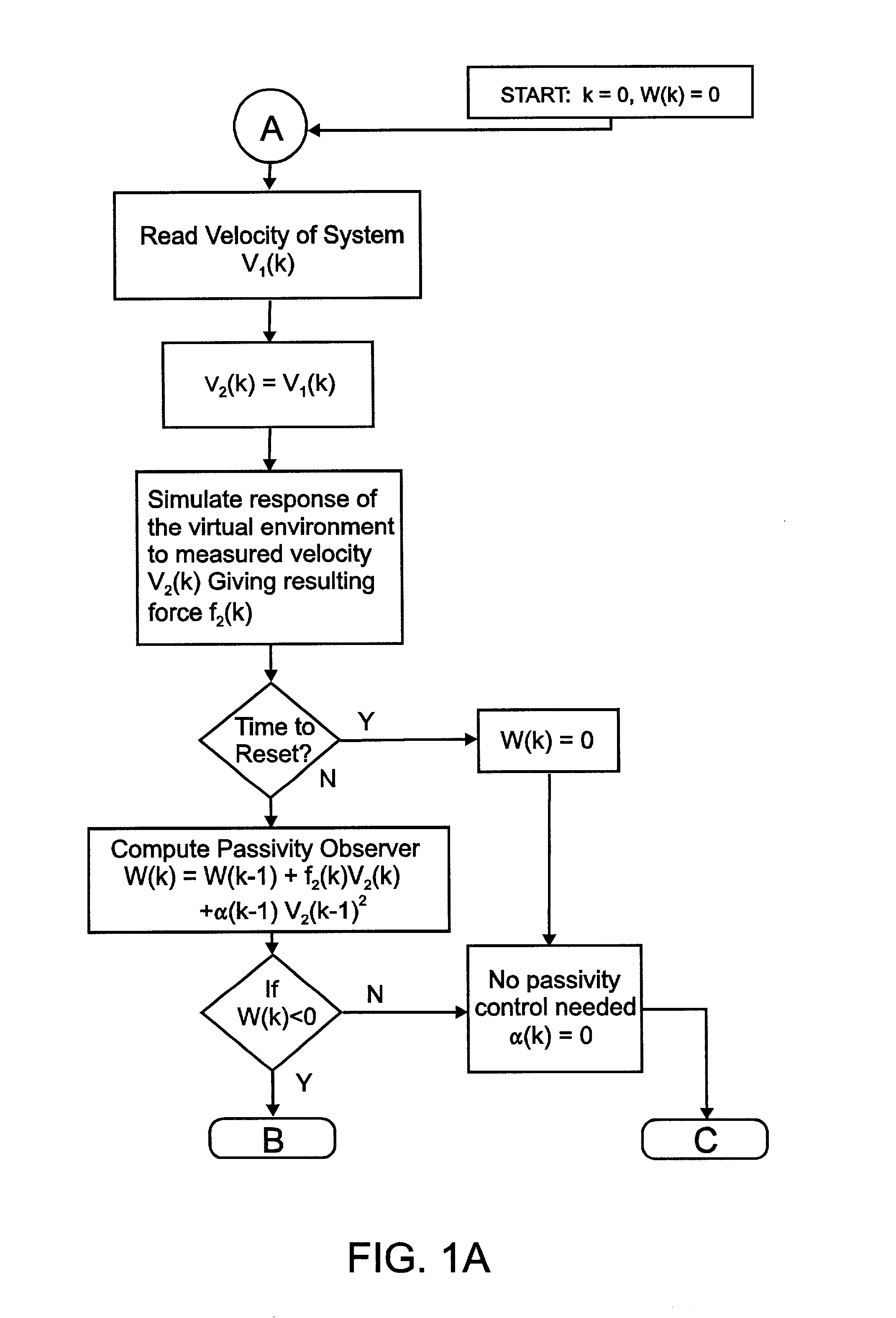
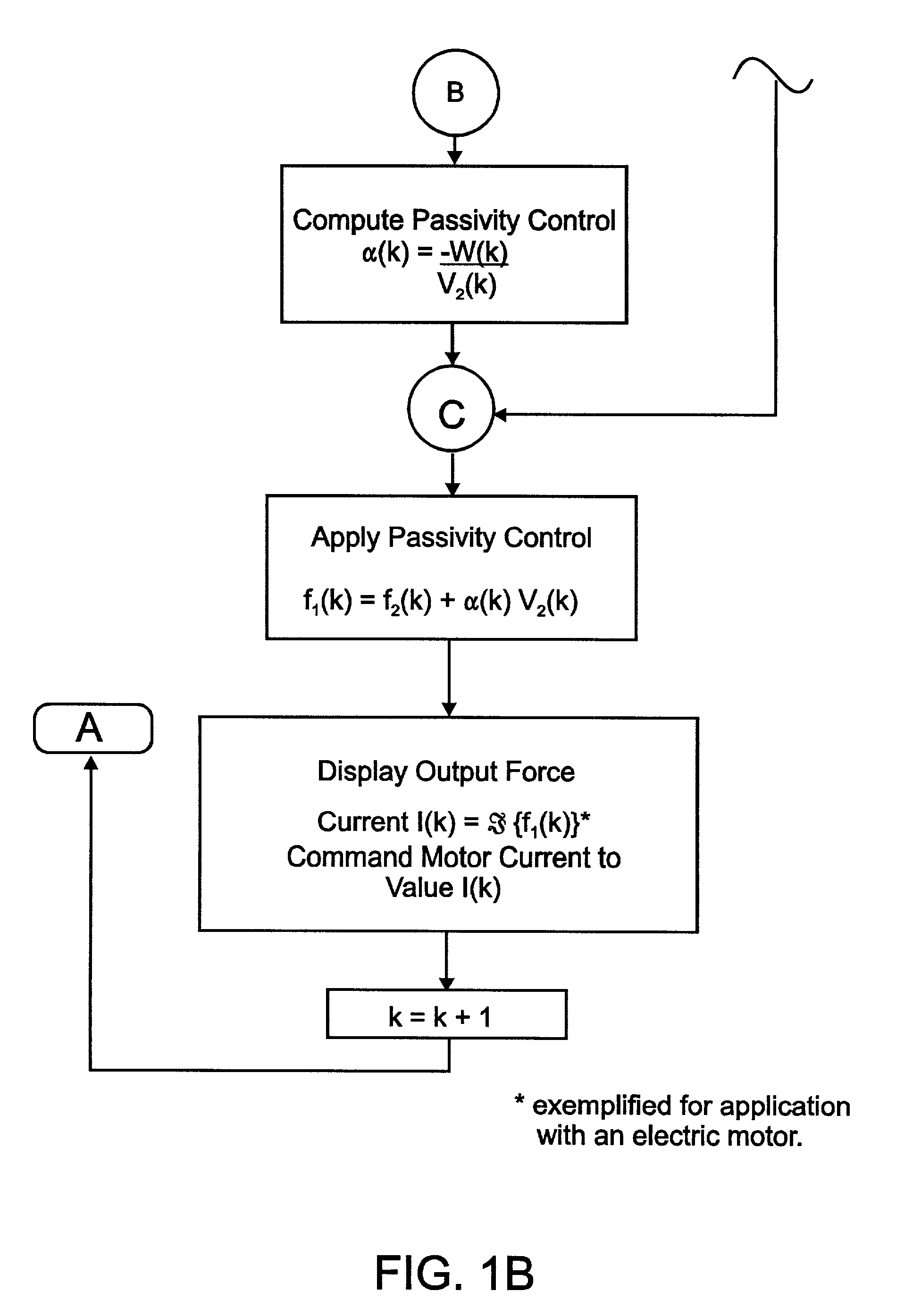
[0169]We illustrate the operation of the Passivity Observer and Passivity Controller with simulation of a simple virtual wall with impedance causality (velocity in, force out). Two separate simulations, one in Matlab / simulink, and one in a C program using trapezoidal integration, were used. The wall consists of a first order, penalty based, spring damper model (FIG. 10) executed at 1000 Hz. We can easily create active behavior of this system by setting the damping parameter, b, to a negative value. The wall generates forces only when x(t)>0. In our simulation, the wall is probed by a point following a sinusoidal velocity trajectory (FIG. 11a). With positive damping (k=710 N / m, b=50 Ns / m, FIG. 11b), the Passivity Observer value increased with time although not monotonically. When the damping parameter is changed to a negative value (b=−50 Ns / m, FIG. 11c) the Passivity Observer returns after each “bounce” to a more negative value, indicating the active behavior of the environment. Fin...


PUM


Abstract

Methods are provided for stabilizing a haptic interface of a computer-controlled one-port virtual-reality system or a two-port teleoperation system comprising a robot manipulator. “Stabilizing” means to reduce the sense of vibration in a haptic interface. A Passivity Observer is computed to measure the amount of energy produced at the haptic interface, and a Passivity Controller is calculated to damp or absorb excess energy which causes the sense of vibration. This invention also provides a “filter,” i.e. a threshold function which returns zero velocity if the computed estimated velocity is less than a small predetermined value, which may be applied to estimated velocities determined in impedance-based methods of this invention so as to remove noise in the velocity estimate. To improve speed of reaction of the systems, this invention also provides methods for resetting the Passivity Observer to zero when it has been too positive for too long a period of time. Systems implementing these methods are also provided.

Description

CROSS-REFERENCE TO RELATED APPLICATIONS[0001]This application claims priority to U.S. Patent Application Ser. No. 60 / 232,134 filed Sep. 13, 2000 and U.S. Patent Application Ser. No. 60 / 292,135 filed May 18, 2001, both of which are incorporated herein by reference to the extent not inconsistent herewith.BACKGROUND OF THE INVENTION[0002]Humans interact with their surrounding environment through five sensory channels, popularly labeled “sight,”“sound,”“taste,”“smell,” and “touch.” It is our sense of touch which provides us with much of the information necessary to modify and manipulate the world around us. The word haptic refers to something “of or relating to the sense of touch” (Hogan, N., “Impedance Control: An Approach to Manipulation: Part I—Theory,” Journal of Dynamic Systems, Measurement, and Control, vol. 107, pp. 1–7, 1985) conveying information on physical properties such as inertia, friction, compliance, temperature, and roughness. This sense can be divided into two categori...

Claims


Application Information

Patent Timeline
IPC IPC(8): G06F17/10G06F3/00B25J9/16G05B5/01G05B13/02G06F3/01G06F19/00
CPCB25J9/1689G05B5/01G06F3/016G05B13/021G05B2219/40122G05B2219/40137
Inventor HANNAFORD, BLAKERYU, JEE-HWAN
Owner UNIV OF WASHINGTON
Learn More