Method of real-time business collaboration

a real-time business and collaboration technology, applied in the field of real-time business collaboration, can solve the problems of large drain on the computer system resources of individual client computer systems, large drain on network resources (e.g., internet bandwidth), and inability to communicate in general,

Inactive Publication Date: 2006-04-11
UGS PLM SOLUTIONS INC
View PDF9 Cites 28 Cited by
  • Summary
  • Abstract
  • Description
  • Claims
  • Application Information

AI Technical Summary

Benefits of technology

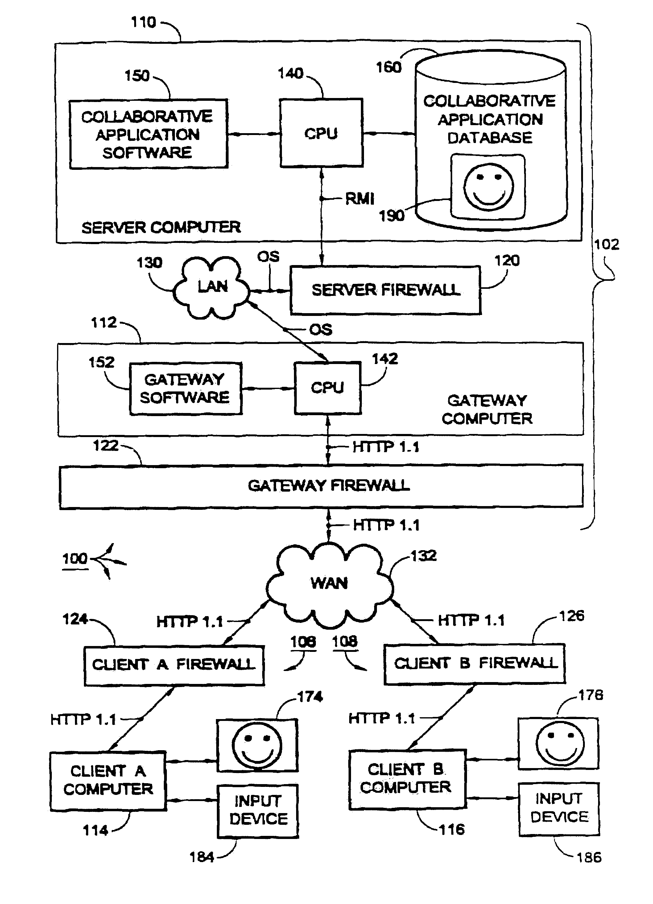
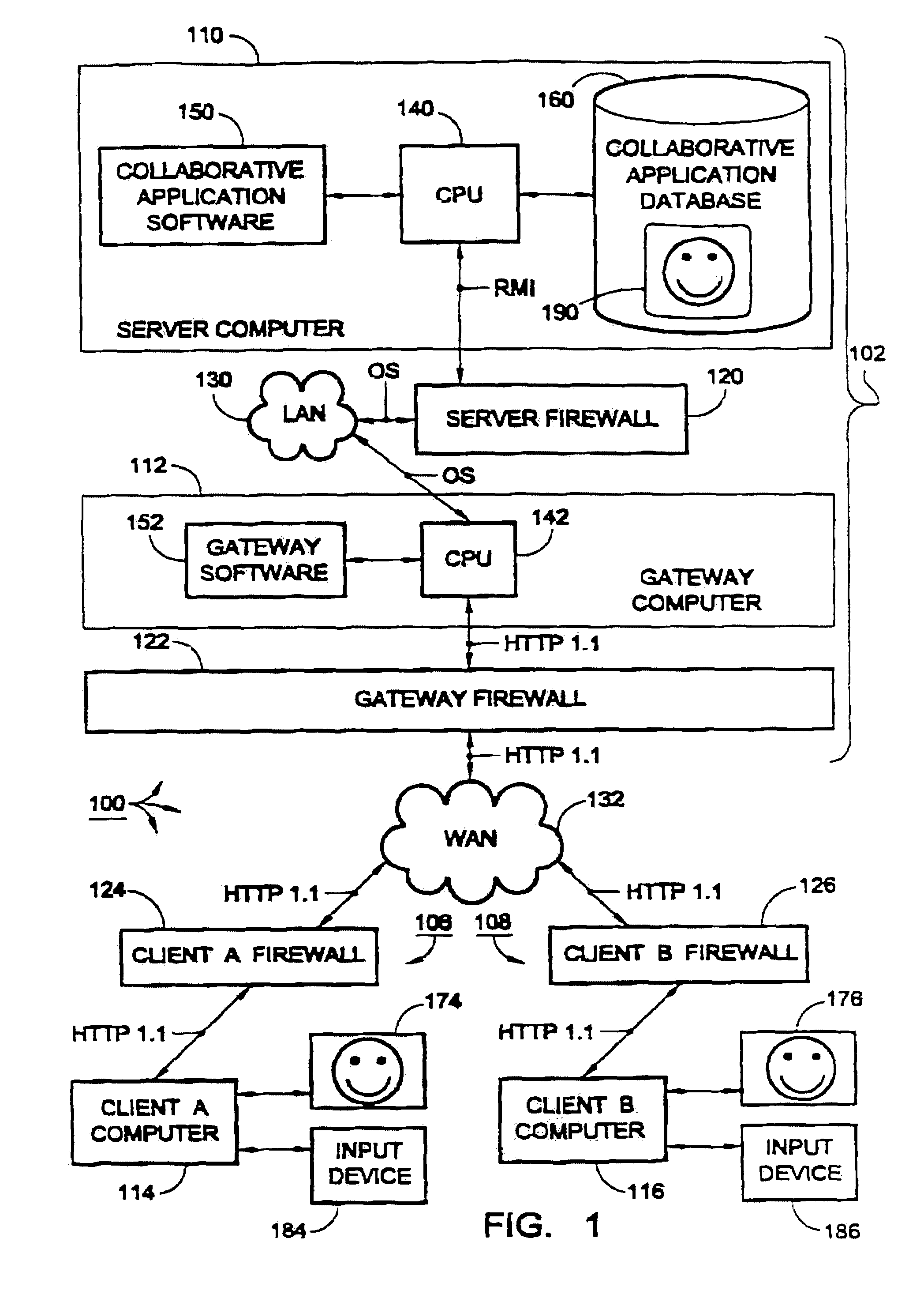
[0012]Given these imperatives, some embodiments of the present invention have a computer program for translating between protocols so that data communications manifest different and optimal transport protocols at both the server and client ends of the computer system. For example, some firewalls (usually client firewalls) are highly amenable to stateful, HTTP 1.1 keep-alive connections via port 80. Other types of firewalls (usually server firewalls) are configured

Problems solved by technology

However, the communication does not, in fact, generally take place over any single dedicated wire or wireless path.
Instead there is a complex system of packet switching that sends various portions of a data communication over various paths, depending primarily on what paths are most readily available to transmit the data.
However, the numerous, successive intermittent communications are required to ensure that any new data added at the server end is quickly requested and received at the client end (to facilitate real-time collaboration) can cause a large drain on the computer system resources of the individual client computer systems, as well as on network resources (e.g., Internet bandwidth).
This problem is exacerbated when any new, relevant server data must get to the client system(s) with sufficient speed so that users of the client computer system(s) perceive t

Method used


Image

  • Method of real-time business collaboration
  • Method of real-time business collaboration
  • Method of real-time business collaboration

Examples


Embodiment Construction

[0026]Before commencing a description of the Figures, some terms will now be defined.

Definitions

[0027]gateway software: machine readable instructions for translating data (e.g. data packets) between two different protocols; it is noted that “gateway” is used here in its well-established nominative sense, and does not refer to the goods, services or affiliations of any particular commercial entity.[0028]computer network: is inclusive of wired networks, wireless networks and hybrid networks including wireless and wired portions.[0029]computer system: computer or network of computers.[0030]computer subsystem: a computer or network of computers; usually part of a larger system.[0031]transport protocol: any computer data protocol that affects the manner in which data is handled at a firewall; it is noted that protocols are conventionally organized according to a hierarchy of protocols of several levels, such as transmission control level protocols, internet level protocols, IP level data...


PUM


Abstract

Computer architecture and software for computer network communication such that data is at least partially converted between distinct transport protocols in order to optimize transmission of the data, and preferably to allow persistent connections to be maintained across different firewalls. As a preferred embodiment, the transport protocol conversion may cause the data to be converted between HTTP 1.1 protocol, to allow a persistent connection originated across port 80 of a first firewall, and a different protocol, to allow a persistent connection across a second firewall. The protocol conversion of the present invention is especially useful in connection with collaborative application software, wherein the collaborative server and its associated clients are respectively more amenable to different transport protocols.

Description

[0001]The present invention is directed to computer networks, such as the Internet, and more particularly to manipulation of network communication protocols and data format of data communicated over a computer network for the purposes of real-time collaboration.BACKGROUND OF THE INVENTION[0002]Computer networks have turned out to be an important communication tool for business, pleasure and governmental purposes. For example, employees of a large business may communicate over an intranet of networked computers. There are also computer networks with wider scope. Of course, the Internet is currently the most prevalent computer network these days. The Internet serves as a sort of meta-network to connect a great many individual computers, intranets and other, smaller-scale networks into a vast global network. While the technical specifics of the Internet may change or evolve over time, there will probably continue to be small-scale computer networks, as well as one or more computer netw...

Claims


Application Information

Patent Timeline
IPC IPC(8): G06F17/30G06F13/00H04L29/06H04L29/08
CPCH04L63/0209H04L67/14H04L67/02H04L69/329H04L67/142Y10S707/99948Y10S707/99931Y10S707/99945
Inventor MCMULLAN, SCOTT R.MEAGHER, DAVID M.
Owner UGS PLM SOLUTIONS INC
Why Eureka
Try Eureka