Fire-resistant door

a door and laminate technology, applied in the direction of wing accessories, carpet fasteners, mechanical equipment, etc., can solve the problems of increasing the weight of the door, causing safety hazards, and not providing sufficient insulation properties

a door and laminate technology, applied in the direction of wing accessories, carpet fasteners, mechanical equipment, etc., can solve the problems of increasing the weight of the door, causing safety hazards, and not providing sufficient insulation properties

US7028431B2Inactive Publication Date: 2006-04-18NYSTROM

Image

  • Fire-resistant door
  • Fire-resistant door
  • Fire-resistant door

Examples


Embodiment Construction

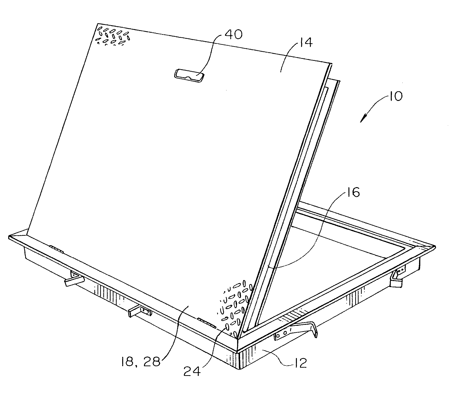
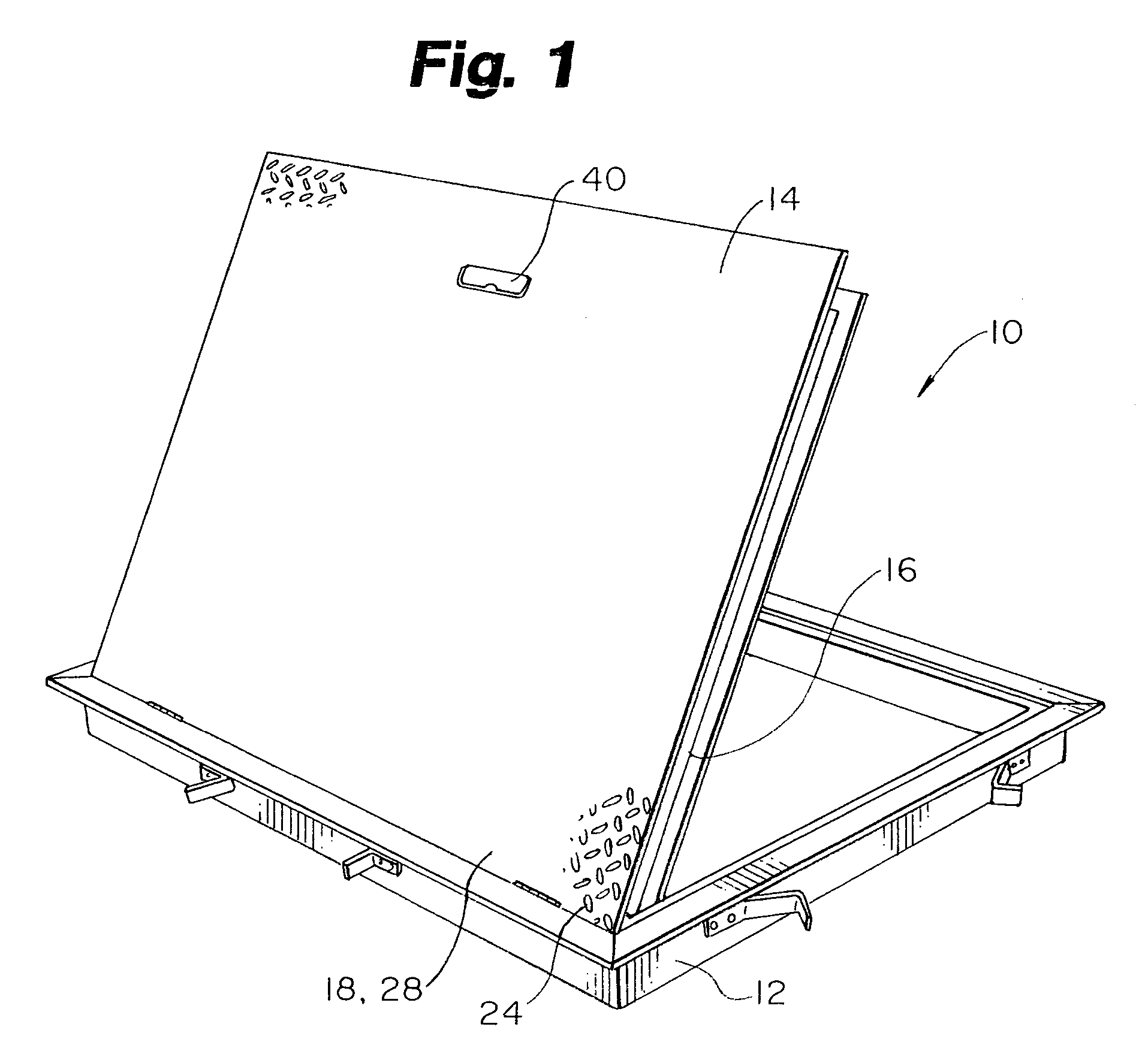
[0032]The fire-resistant door of the present invention is generally shown in the Figures as reference numeral 10.

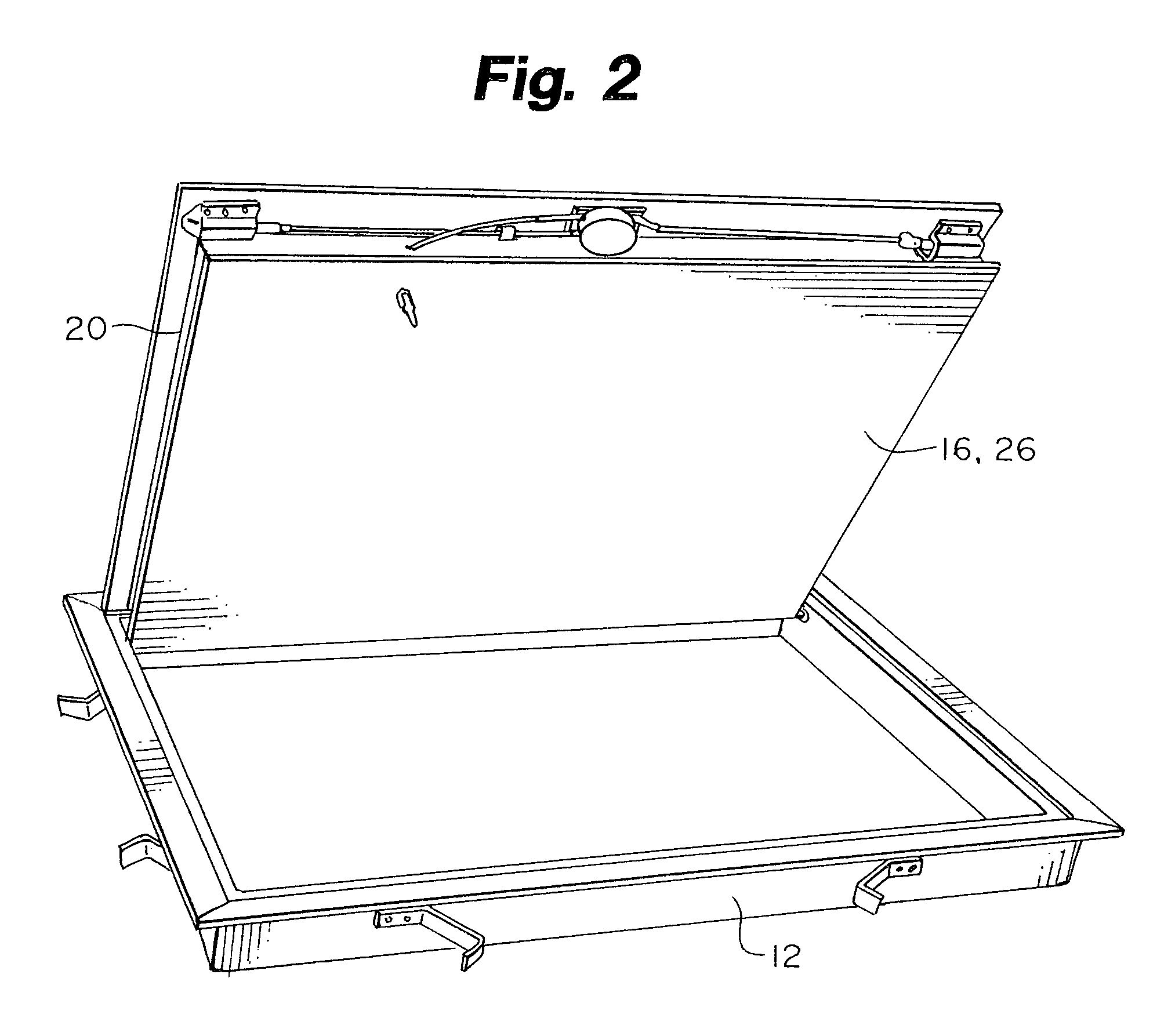
[0033]The door 10 comprises a door frame 12, a door 14 hingedly mounted on the frame 12 the door having a bottom wall 16, top wall 18, and side walls 20.

[0034]The bottom wall 16, top wall 18, and side walls 20 enclose a hollow central core 22.

[0035]The door 14 is hingedly connected to the frame 12 by hinges 24.

[0036]The bottom wall 16 has an outside surface 26 and the top wall 18 has an outside surface 28.

[0037]A layer of intumescent material 30 is applied to the outside surface 26 of the bottom wall 16. The frame 12 also has a bottom wall 13 to which intumescent material 30 may be applied.

[0038]Preferably, the top wall 18, bottom wall 16, and side walls 20 comprise aluminum material.

[0039]The door frame 12 has a flange 32 adapted to engage the door when closed. A fiberglass gasket 34 is attached to the flange to provide an insulating seal between the door 14 and the flan...


PUM


Abstract

A fire-resistant, aluminum, cementitious-material-free, insulation-free door adapted to prevent the spread of fire and heat passing therethrough, consists of: a door frame, a door hingedly mounted on the door frame, the door having a bottom wall, a top wall, and side walls, the bottom wall, top wall and side walls enclosing a hollow central core not containing substantial amounts of insulating material, the bottom wall having an outside surface, and the top wall having an outside surface; and a layer of intumescent material on the outside surface of the bottom wall. A heat-activated self-closing mechanism allows the weight of the door to close the door in the vent of fire, by releasing gas from a supporting gas spring.

Description

RELATED APPLICATION[0001]This application is a continuation of application Ser. No. 09 / 598,563 filed Jun. 21, 2000, now U.S. Pat. No. 6,615,544.BACKGROUND OF THE INVENTION[0002]The present invention relates to a fire-resistant laminate structure and more particularly to horizontally hinged doors for floors that have a high fire rating and which use an automatic control system to automatically close the door in a fire.[0003]The need for fire resistant structures is self-evident and building codes have been passed by governments to ensure that public safety is protected. Such building codes mandate fire-resistant materials such as panels and mechanisms to prevent the spread of fire. Structures such as floors, ceilings, and doors must have resistance to the path of the fire and many techniques have been used to produce such fire resistance.[0004]Horizontally-hinged doors may be used for access doors, roof scuttles, automatic fire vents, ceiling access doors, etc., to provide access fro...

Claims


Application Information

Patent Timeline
18 Apr 2006
Publication
US7028431B2
IPC
E05F15/20; E05F1/00; E05F1/10
CPC
E05F1/006; E05B65/104; E05F1/1091; E05Y2201/41; E05Y2900/612; Y10S292/65; Y10S292/66; E05Y2201/50
Inventors
TLEMCANI, JALIL; CARROLL, MICHAEL J.