Air-conditioning system for vehicle

Inactive Publication Date: 2006-04-18
SANDEN CORP
View PDF19 Cites 9 Cited by
  • Summary
  • Abstract
  • Description
  • Claims
  • Application Information

AI Technical Summary

Benefits of technology

[0008]Accordingly, it is an object of the invention to provide an air-conditioning system for a vehicle, which pre

Problems solved by technology

However, the use of such a refrigerant in the known air-conditioning system discussed above raises the following problems.
In a case where the damaged part of the air-conditioning system lies in the refrigerant circulation passage in the instrument space therefor between the engine room and the vehicle com

Method used


Image

  • Air-conditioning system for vehicle
  • Air-conditioning system for vehicle
  • Air-conditioning system for vehicle

Examples


Example

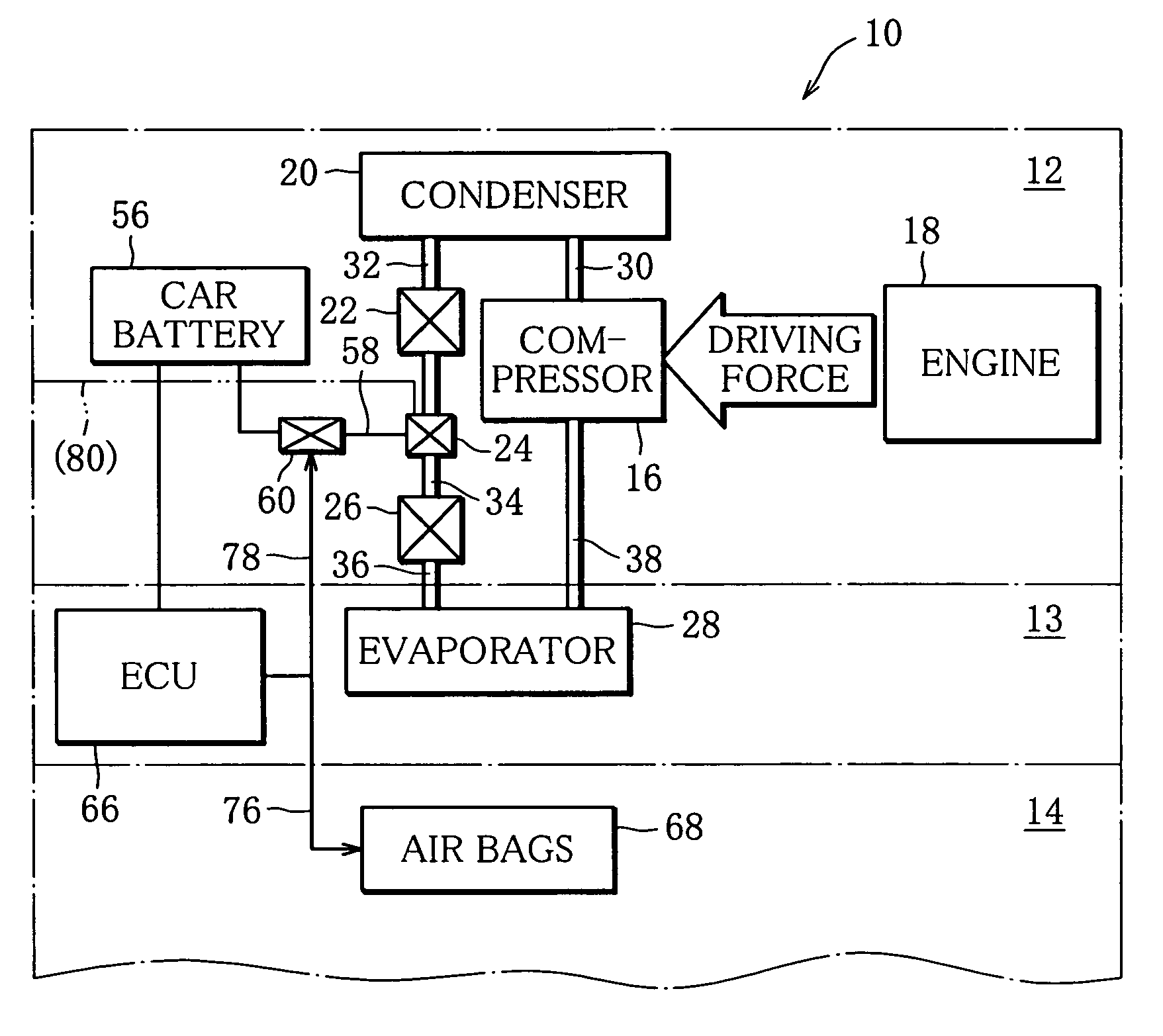
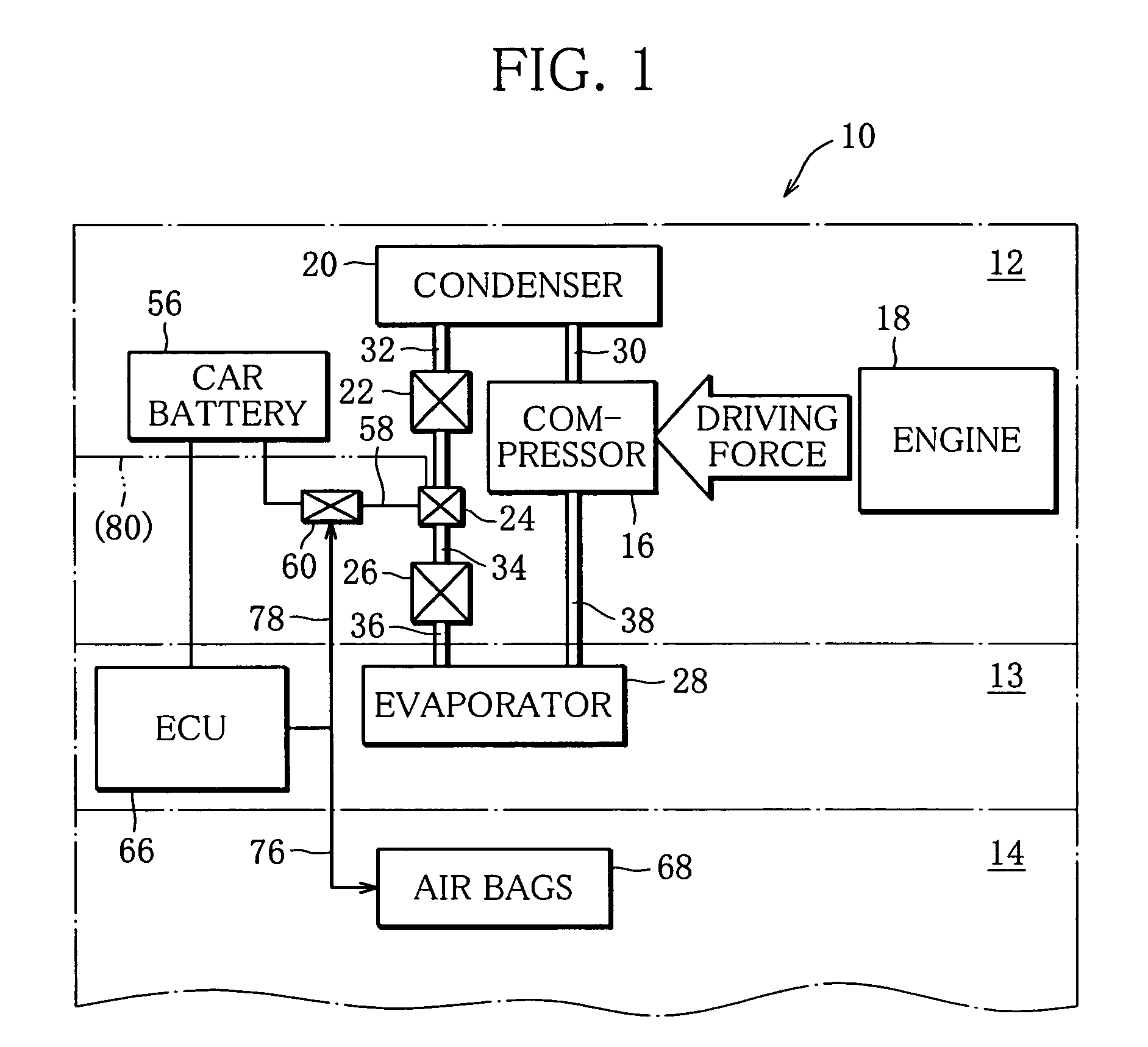
[0025]As shown in FIG. 1, an air-conditioning system 10 for a vehicle has a circulation passage extending from an engine room 12 of the vehicle into an instrument space 13 located between the engine room 12 and vehicle compartment 14. The system can adjust the temperature inside the vehicle compartment 14 to a desirable set temperature using the latent heat of a refrigerant that flows in the circulation passage.

[0026]A compressor 16 is disposed in the circulation passage in the engine room 12 and is operated by the driving force of an engine 18 housed in the engine room 12. The compressor 16 sucks the gaseous refrigerant through a suction port thereof, compresses the refrigerant therein and delivers the refrigerant as a high-temperature and high-pressure gas toward the downstream of the circulation passage from a discharge port thereof. That is, the compressor 16 creates the flow of the refrigerant while compressing the refrigerant.

[0027]A condenser 20 is disposed in the circulation...


PUM


Abstract

An air-conditioning system for a vehicle includes an electronic control unit which detects a collision of the vehicle and activates an air bag of the vehicle, and a circulation passage for a refrigerant or R152a. The system further includes a discharge device which discharges the refrigerant from the circulation passage in the engine room when the control unit outputs an air-bag activation signal. The discharge device includes an electromagnetic valve adapted to opened to discharge a refrigerant from the circulation passage in the engine room when the control unit outputs the signal.

Description

[0001]This nonprovisional application claims priority under 35 U.S.C. §119(a) on Patent Application No. 2003-149470 filed in Japan on May 27, 2003, the entire contents of which are hereby incorporated by reference.BACKGROUND OF THE INVENTION[0002]1. Field of the Invention[0003]The present invention relates to an air-conditioning system for a vehicle, and, more particularly, to an air-conditioning system suitable for usage of a refrigerant having a small global warming potential.[0004]2. Description of the Related Art[0005]Various kinds of measure to guarantee safety of vehicles are proposed for air-conditioning systems. One air-conditioning system equipped with such safety measure is disclosed in, for example, Japanese Utility Model Publication No. S56-40182 / 1981. The known safety measure has a safety valve disposed in a high-pressure portion of a refrigerant circulation passage. The safety valve is designed in such a way that when the pressure in the high-pressure portion rises abn...

Claims


Application Information

Patent Timeline
IPC IPC(8): B60H1/32B60H1/22B60H1/00
CPCB60H1/00978B60H1/3225B60H1/3217
Inventor KOMATSU, SHUNJI
Owner SANDEN CORP
Why Eureka
Try Eureka