

Body motion detector
a motion detector and body technology, applied in the field of body motion detectors, can solve problems such as user burden
- Summary
- Abstract
- Description
- Claims
- Application Information
AI Technical Summary
Benefits of technology
Problems solved by technology
Method used
Image

Examples
first embodiment
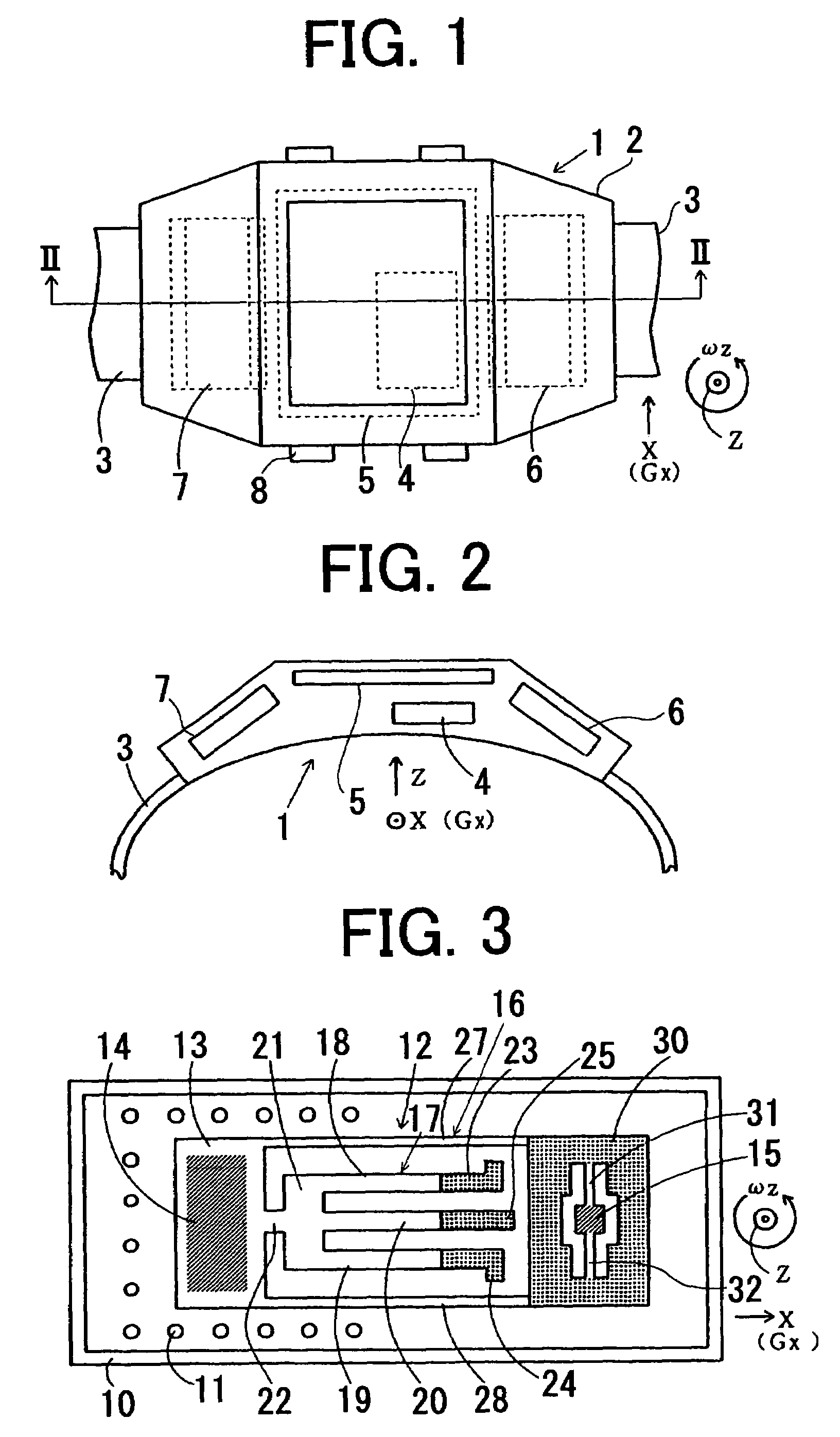
[0054]a physical movement detecting and analyzing device according to the present invention will now be described. FIG. 1 is a plan view of a movement measuring device, and FIG. 2 is a sectional view taken along a line II—II of FIG. 1. A movement measuring device 1 comprises a case 2 having a shape of a watch and which can be worn on a wrist of a user by a pair of bands 3 wrapped around the wrist. The case 2 is provided with a movement sensor 4, liquid crystal display 5, transmission circuit module 6 for external communication, power supply battery 7, and manipulating switches 8. The movement measuring device 1 is rendered thin and small so as not to burden the user. The display 5 is disposed on the largest surface of the device so as to be easily viewed. The movement sensor 4 is disposed in parallel to the display 5. The display 5 which is a liquid crystal display panel is small in thickness and the movement sensor 4 is contained in a thin package.
[0055]The movement sensor 4 is ada...
second embodiment
[0090]FIG. 14 is a plan view showing the movement measuring device of the present invention, and FIG. 15 is a sectional view taken along a center line thereof. The present embodiment is adapted mainly to a device for transmitting an intension of a user to a third party.
[0091]Referring to FIG. 14, a case 60 of a movement measuring device 58 is provided with a display window 61 and a plurality of manipulating switches 62. In the case, there are provided a movement sensor 63, liquid crystal display 64, and a circuit board 65 on which an IC for a display driving circuit and a control circuit are mounted.
[0092]In addition, there are further provided power supply batteries 66, transmission module 67 having a transmitting and receiving IC, and a transmission substrate 68 on which the IC and an antenna of the transmission module 67 are mounted.
[0093]The case 60 is worn on a wrist with a band 70 wound around thereof. When a gesture or hand motion for a sign is made, information corresponding...
third embodiment
[0114]FIG. 22a is a plan view showing a specific example of a triaxis acceleration sensor provided in the third embodiment, and FIG. 22b is a sectional view thereof. The sensor of the present embodiment, for detecting three axes X, Y, and Z acceleration, is made of a machined phosphorus bronze block and has a supporter 130, metal disk 131 and a central shaft 132 mounted on the supporter, and a piezoelectric plate 133 secured on the circular plate. An annular mass loading element 134 is attached to the central shaft by force fit.
[0115]The piezoelectric plate 133 is made of a piezoelectric magnetic material such as lead zirconate titanate polarized in the direction of the thickness of the plate. On the upper surface of the plate, there are provided semicircular X-electrode films 135, 136, Y-electrode films 137, 138 and Z-electrode films 140, 141, 142, 143 each of which having an area approximately the half as those of other electrodes. The electrodes are formed by vapor deposition. Th...
PUM
 Abstract
Description
Claims
Application Information