
Wheel suspension for a motor vehicle with a transverse leaf spring

a technology of transverse leaf spring and suspension, which is applied in the direction of spring/damper, mechanical apparatus, transportation and packaging, etc., can solve the problems of undesirable change in toe-in and considerable change in tread width, and achieve the effect of low weight and without disadvantages in kinematics and rolling ra

Inactive Publication Date: 2006-04-18
FORD GLOBAL TECH LLC
View PDF34 Cites 19 Cited by
  • Summary
  • Abstract
  • Description
  • Claims
  • Application Information

AI Technical Summary

Benefits of technology

[0003]Against this background, the object of the present invention was to provide an improved wheel suspension with a transverse leaf spring, which, along with a low weight and without disadvantages in terms of kinematics and of rolling rate, integrates the functions of the springing, of various links and preferably also of the stabilizer system.
[0005]By virtue of the transverse leaf spring being shaped with an arc or a bend, a considerably improved driving behavior is achieved, since the bends of the transverse leaf spring which take place during a compression and rebound of the wheels lead to reduced changes in the tread width. Owing to the reduced lateral movement of the wheels, the transverse leaf spring bearings can then be designed with greater lateral rigidity, so that the entire wheel suspension advantageously acquires high lateral rigidity.
[0008]According to a development of the invention, the transverse leaf spring is designed nonuniformly along its extent, so that different regions have different elastic properties. In particular, in this case, a middle region of the transverse leaf spring may have a flat design (for example, with a flatly rectangular cross section), while at least one wheel-side end region of the transverse leaf spring has a compact, preferably square or round or circular cross section. The middle region then possesses high flexibility in one direction, so that it can effectively assume the functions of a spring and of a stabilizer. By contrast, the end region may be designed rigidly for all the load directions, in order thereby to be able to absorb the braking forces and lateral forces. It may, however, also be subjected to torsional stress and thus assume the function of the stabilizer.
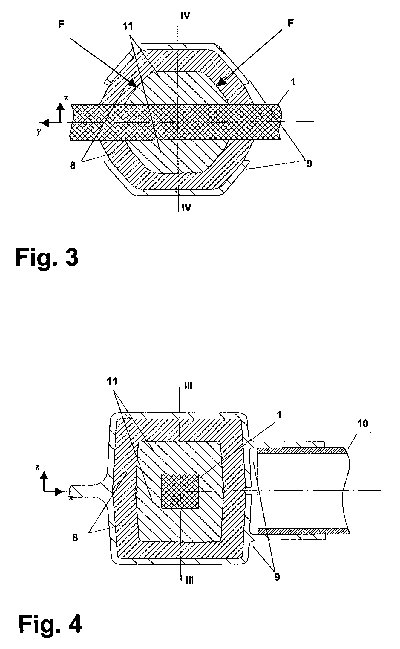
[0013]Another further development relates to a special embodiment of the transverse leaf spring bearings, with bearings of this type being capable of being used advantageously not only in wheel suspensions according to the present invention, but also in other types of wheel suspensions (with or without a transverse leaf spring). The transverse leaf spring bearings according to the invention have a thickening which surrounds the transverse leaf spring, the axial ends of the thickening (with respect to the axis of the transverse leaf spring) consisting of essentially planar surface pieces. Said surface pieces are in this case inclined at a relatively steep angle of typically 45° to 90° in relation to the axis of the transverse leaf spring. A high lateral rigidity of the transverse leaf spring bearing is thereby achieved. A slight inclination of the surface pieces with respect to a position perpendicular to the axis (90° angle) is in this case advantageous in terms of the assembly of the bearing.

Problems solved by technology

In this and similar approaches, however, there is the problem that the movement of the compression and rebound of the wheels which takes place in the vertical direction leads to a considerable change in the tread width, which, in turn, results in an undesirable change in the toe-in.

Method used


Image

  • Wheel suspension for a motor vehicle with a transverse leaf spring
  • Wheel suspension for a motor vehicle with a transverse leaf spring
  • Wheel suspension for a motor vehicle with a transverse leaf spring

Examples


Embodiment Construction

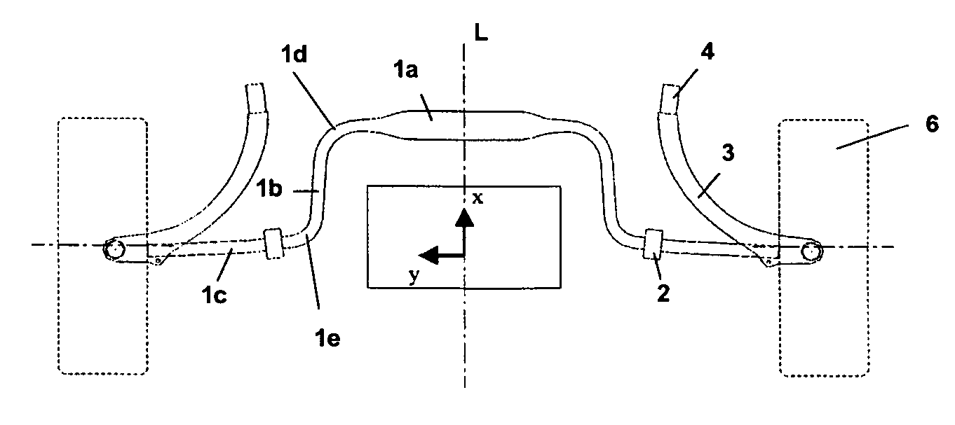
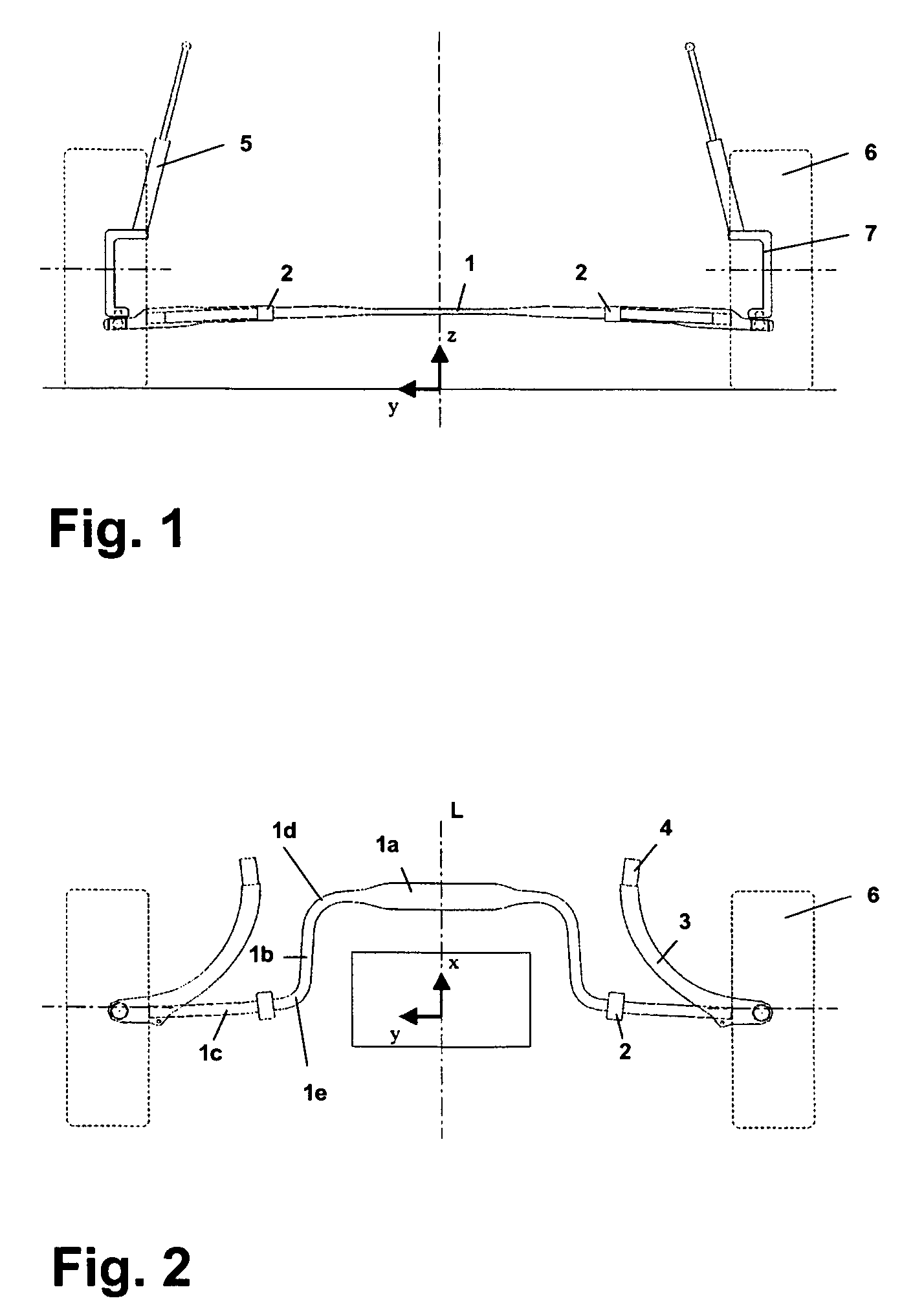
[0021]FIGS. 1 and 2 show two different views of a wheel suspension according to the invention by the example of the front wheels, although the wheel suspension can also be implemented in a similar way with regard to the rear wheels.

[0022]The central element of the wheel suspension is a transverse leaf spring 1 which extends between the two wheels 6 transversely to the vehicle longitudinal axis L pointing in the x-direction and which is articulated at its ends on the wheel carriers 7. As can be seen in the front view of FIG. 1, the transverse leaf spring 1 extends with a slight upward curvature in a plane parallel to the road.

[0023]According to the top view of FIG. 2, the particular feature of the transverse leaf spring 1 is that it has, on both sides of the middle region 1a, arcs 1d of approximately 90° which connect the middle region 1a to torsional portions 1b running in the direction of the vehicle axis L. The torsional portions 1b are, in turn, connected to end portions 1c of th...


PUM


Abstract

A wheel suspension with a transverse leaf spring (1a–1c) which is articulated at both ends on wheel carriers. The transverse leaf spring shaped symmetrically to the vehicle longitudinal axis (L) has a curved profile with a middle region (1a) offset parallel to the wheel axis. The transverse leaf spring is supported on the vehicle body by means of two transverse leaf spring bearings (2) with high lateral rigidity. The curved profile of the transverse leaf spring with four arcs (1d, 1e) allows for a bending of the middle region (1a) to take place essentially without a change in the tread width.

Description

BACKGROUND OF THE INVENTION[0001]The invention relates to a wheel suspension for a motor vehicle with a transverse leaf spring which is arranged transversely to the vehicle and which is connected to the motor vehicle body via at least one transverse leaf spring bearing and is articulated on at least one wheel carrier.[0002]A wheel suspension of the type initially mentioned is known from EP 1 080 953 A1, the transverse leaf spring described there being shaped symmetrically in relation to the vehicle longitudinal mid-plane, being mounted on both sides and being supported at both ends via spring arms. In this arrangement, the transverse leaf spring replaces the helical spring present in conventional wheel suspensions, and also the stabilizer and further link arms. In this and similar approaches, however, there is the problem that the movement of the compression and rebound of the wheels which takes place in the vertical direction leads to a considerable change in the tread width, which...

Claims


Application Information

Patent Timeline
IPC IPC(8): B60G21/055B60G11/08B60G3/28B60G11/44F16F1/18
CPCB60G11/08B60G21/051B60G11/44B60G2206/7101B60G2200/142B60G2200/1422B60G2202/114B60G2202/1424B60G2204/121B60G2204/41B60G2204/82B60G2204/8302B60G2206/013B60G2206/20B60G2206/42B60G2206/427
Inventor ZANDBERGEN, PAULCHAMBERS, SHAWN
Owner FORD GLOBAL TECH LLC
Learn More