This helps you quickly interpret patents by identifying the three key elements:
Problems solved by technology
Method used
Benefits of technology
Benefits of technology
[0009]Accordingly, it is an object of the invention to provide a light emitting apparatus that, while making the best use of a feature of LED, i.e., a small thickness, can realize impressive illumination of an elongated shape by one light emitting device and can realize high external emission efficiency.
Problems solved by technology
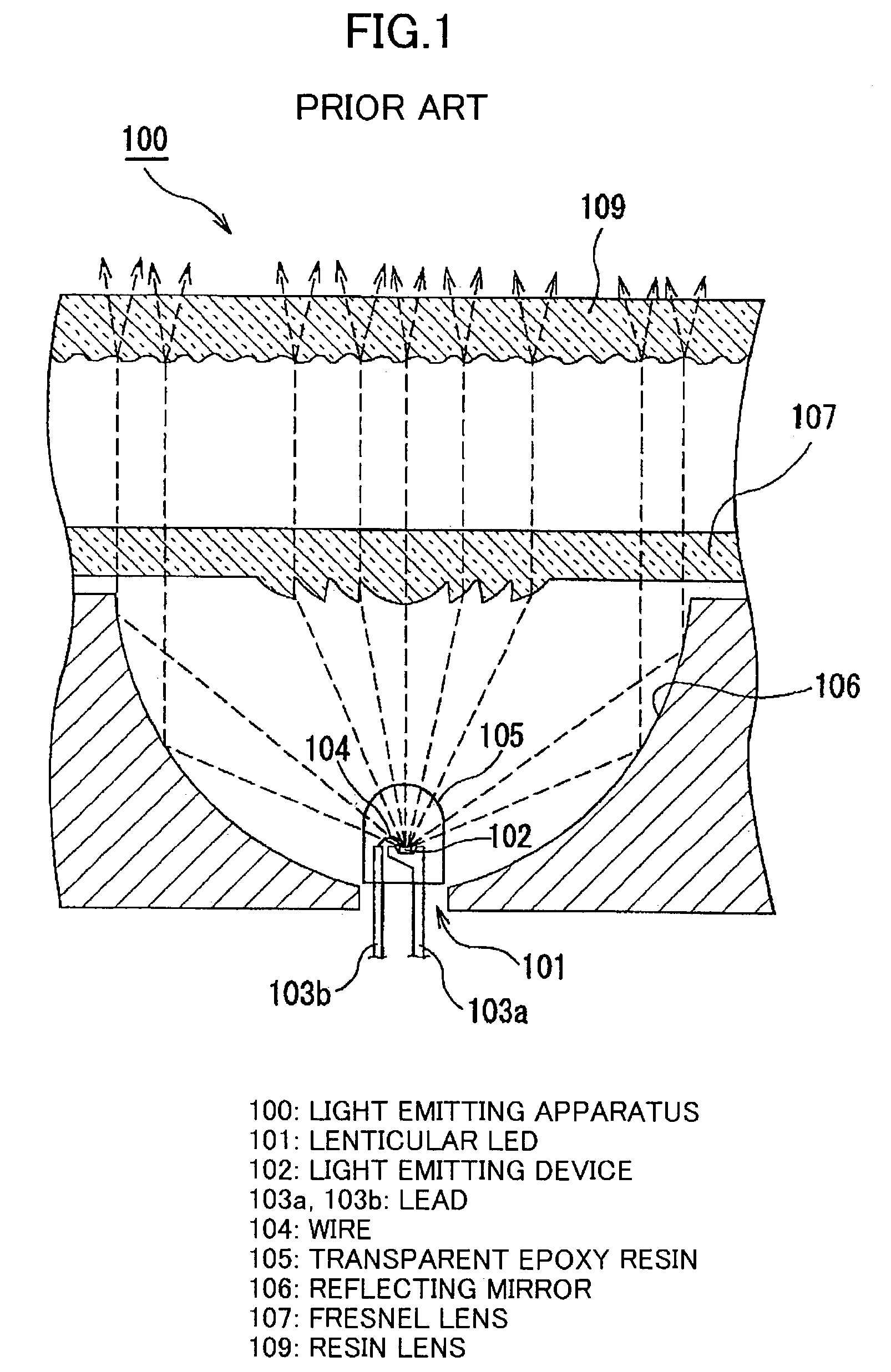
This poses a problem that a thin light source, which is a feature of the LED, cannot be produced.
Method used
Image
Click on the blue label to locate the original text in one second.
Reading with bidirectional positioning of images and text.
Examples
first preferred embodiment
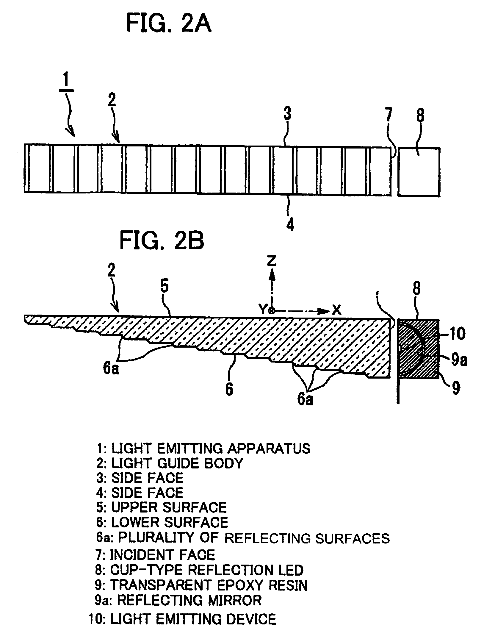
[0044]The first preferred embodiment 1 of the invention will be explained in conjunction with FIGS. 2A, 2B, and 3.
[0045]FIG. 2A is a plan view showing the whole construction of the light emitting apparatus in a first preferred embodiment of the invention, FIG. 2B a longitudinal sectional view of the light emitting apparatus shown in FIG. 2A, and FIG. 3 a front view showing the whole construction of a display using the light emitting apparatus in the first preferred embodiment of the invention.
[0046]As shown in FIGS. 2A and 2B, the light emitting apparatus 1 according to preferred embodiment 1 comprises a light guide body 2 of which the body is formed of a transparent acrylic resin. A cup-type reflection LED 8 is provided contiguously to the light guide body 2. The upper surface 5 of the light guide body 2 is flat. On the other hand, the lower surface 6 of the light guide body 2 is in the form of a stepped reflecting mirror provided with a plurality of reflecting surfaces 6a. As show...
embodiment 2
Preferred Embodiment 2
[0053]Next, the second preferred embodiment of the invention will be explained in conjunction with FIGS. 4A and 4B. FIG. 4A is a cross-sectional view showing the construction of a light emitting section in a light emitting apparatus 12 in the second preferred embodiment of the invention, and FIG. 4B a front view of the light emitting section in the light emitting apparatus 12 shown in FIG. 4A.
[0054]As is shown in FIGS. 4A and 4B, the light emitting apparatus 12 in the second preferred embodiment comprises a metal base substrate 17. A circuit board 15 is provided on the metal base substrate 17 through an insulating layer 16. A light emitting device 14 is mounted on the circuit board 15. The focal point of the reflecting surface 13, which faces the light emitting surface of the light emitting device 14, is the light emitting surface of the light emitting device 14. The light reflecting surface 13 comprises a paraboloid 13a of revolution having a central axis iden...
third preferred embodiment
[0058]A light emitting apparatus according to the third preferred embodiment of the invention will be explained in conjunction with FIGS. 5A, 5B, and 5C. FIG. 5A is a plan view showing the construction of a light guide body 18 in a light emitting apparatus in the third preferred embodiment of the invention, FIG. 5B a cross-sectional view taken on line A—A of FIG. 5A, and FIG. 5C a cross-sectional view taken on line B—B of FIG. 5A.
[0059]As shown in FIGS. 5A, 5B, and 5C, in the light guide body 18 in the third preferred embodiment, the reflecting surface is split in the direction of Y, as well as in the direction of X, that is, split into reflecting surfaces 21a, 21b, 21c. In this case, the positions of the reflecting surfaces in the direction of X are shifted, and the pitch of the reflecting surfaces 21a, the pitch of the reflecting surfaces 21b, and the pitch of the reflecting surfaces 21c are intentionally made long. According to this construction, unlike the first preferred embodi...
PUM
Abstract
An opposed reflecting mirror is provided so as to face a light source. The opposed reflecting mirror is configured to reflect light rays, emitted from the light source, so as to allow the reflected light rays to advance in a predetermined direction. A light guide body having a plurality of reflecting surfaces is provided to permit the incidence of light rays supplied from the opposed reflecting mirror and to reflect the incident light rays. The plurality of reflecting surfaces are located at different positions in a sliding split manner along the direction of light rays supplied from the opposed reflecting mirror. By virtue of this construction, a light emitting apparatus can be provided in which, while making the best use of a feature of LED, i.e., a small thickness, impressive illumination of an elongated shape by one light emitting device and high external emission efficiency can be realized. The arrangement of a plurality of light emitting apparatuses of the above type at predetermined intervals can provide on-vehicle or other displays of a novel and unconventional design.
Description
[0001]The present application is based on Japanese Patent Application No. 2001-371586, the entire contents of which are incorporated herein by reference.BACKGROUND OF THE INVENTION[0002]1. Field of the Invention[0003]The invention relates to a light emitting apparatus and a display that, through the utilization of a light emitting device or an LED lamp as a light source, can be applied, for example, to on-vehicle lights or other lighting units, display units and the like.[0004]In this specification, an LED chip per se is referred to as “light emitting device,” and the whole system including an LED chip-mounted package resin or lens system or other optical system is referred to as “light emitting diode,”“LED,” or “light emitting apparatus.”[0005]2. Related Art[0006]An increase in brightness of light emitting devices has led to extensive use of light emitting apparatuses using LEDs as a light source, for example, in backlights of automobiles. LEDs have a narrow-band emission spectrum,...
Claims
Application Information
Patent Timeline
Application Date:The date an application was filed.
Publication Date:The date a patent or application was officially published.
First Publication Date:The earliest publication date of a patent with the same application number.
Issue Date:Publication date of the patent grant document.
PCT Entry Date:The Entry date of PCT National Phase.
Estimated Expiry Date:The statutory expiry date of a patent right according to the Patent Law, and it is the longest term of protection that the patent right can achieve without the termination of the patent right due to other reasons(Term extension factor has been taken into account ).
Invalid Date:Actual expiry date is based on effective date or publication date of legal transaction data of invalid patent.

