
Cover assembly for vacuum electron device

a vacuum electron and cover assembly technology, applied in the direction of transit-tube vessels/containers, coupling device connections, amplifiers with transit-time effects, etc., can solve the problems of rf energy leakage from amplifiers, easy damage of electrical contact fingers in sockets, cumbersome process, etc., to prevent rf leakage, easy assembly and disassembly, good seat alignment

Inactive Publication Date: 2006-04-18
COMM & POWER IND
View PDF27 Cites 4 Cited by
  • Summary
  • Abstract
  • Description
  • Claims
  • Application Information

AI Technical Summary

Benefits of technology

[0012]Accordingly, a need exists for an improved input circuit for an RF amplifier providing a high power output which provides a good seat alignment for the VED with an EMI gasket to prevent RF leakage, an easy assembly and disassembly mechanism, a proper cooling system with RF isolation, and an easy socket interface.

Problems solved by technology

This process can be cumbersome and inconvenient.
During tube replacement, electrical contact fingers in the socket may be easily damaged due to incorrect alignment.
With damage to the contact fingers, RF energy may leak from the amplifier.
RF leakage can also generate a substantial amount of heat or arcing which may damage wiring and components.
In addition, misalignment may also cause RF leakage from the amplifier enclosure due to improper seating on an electro magnetic interference (EMI) gasket.
Even if the input circuit is properly seated, the high voltage leads can couple an undesirable percentage of the input RF into the transmitter's instrumentation.
Due to spatial constraints, it is difficult to isolate the RF signals within the enclosure by loading it with ferrites (filter components, chokes and bobbins).
Despite the ability to combine RF components and high voltage components under the same cover, the spatial constraint limits the ability to improve the product.
Aside from RF isolation, high voltage standoff issues make it difficult to incorporate a quick and easily accessible connection box.
Such components can easily be damaged during assembly or installation of the RF socket.

Method used


Image

  • Cover assembly for vacuum electron device
  • Cover assembly for vacuum electron device
  • Cover assembly for vacuum electron device

Examples


Embodiment Construction

[0043]Embodiments of the present invention are described herein in the context of high power RF amplifiers employing vacuum electron devices. Those of ordinary skill in the art will realize that the following description of the present invention is illustrative only and not intended to be in any way limiting. Other embodiments of the invention will readily suggest themselves to such skilled persons having the benefit of this disclosure. Reference will now be made in detail to implementations of the present invention as illustrated in the accompanying drawings. The same reference numbers will be used throughout the drawings and the following description to refer to the same or like parts.

[0044]In the interest of clarity, not all of the routine features of the implementations described herein are described. It will of course be appreciated that in the development of any such actual implementation, numerous implementation-specific decisions must be made to achieve the developer's speci...


PUM


Abstract

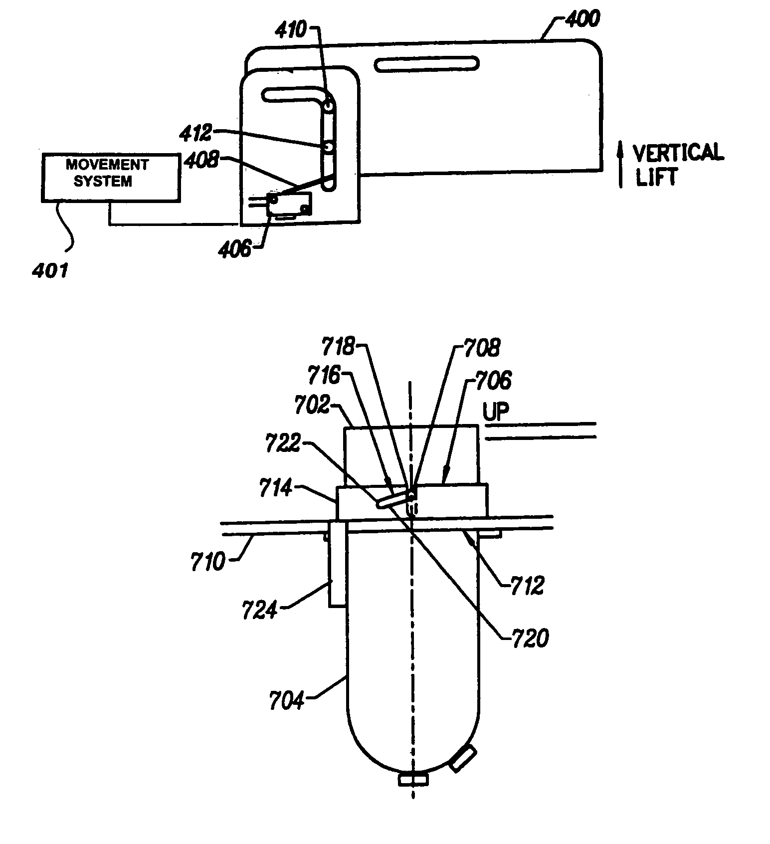
A self guiding cover assembly for a vacuum electron device (VED) enclosure has a cover, a pair of guide plates, and a pair of guide elements. The cover has a top, a sidewall, an inside and an outside, and at least one electrical connector disposed on the inside of the cover for mating with an electrical connector on a VED. The pair of guide plates is disposed on opposite sides of the outside of the sidewall of the cover. The guide plates each have a track. The guide elements are mounted on the enclosure on opposite sides of the cover. The pair of guide elements each mates with the track to guide the cover as it is lifted from the enclosure. The cover further comprises a breach lock mechanism for seating the VED into the VED enclosure having the cover and a base. The breach lock mechanism has guide elements mounted on the cover. A sleeve is mounted on the base and removably receives the cover with the VED. The sleeve rotates about the cover. The sleeve has tracks for mating with the guide elements. A rotation of the sleeve pulls the top into the base for seating the VED.

Description

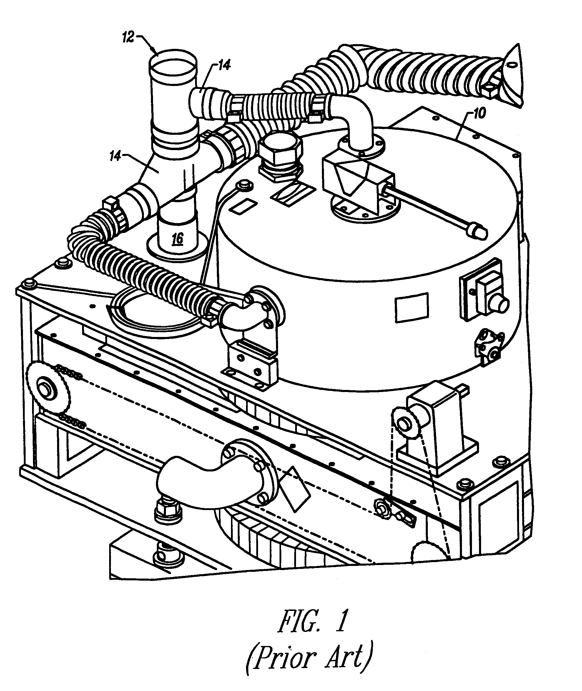
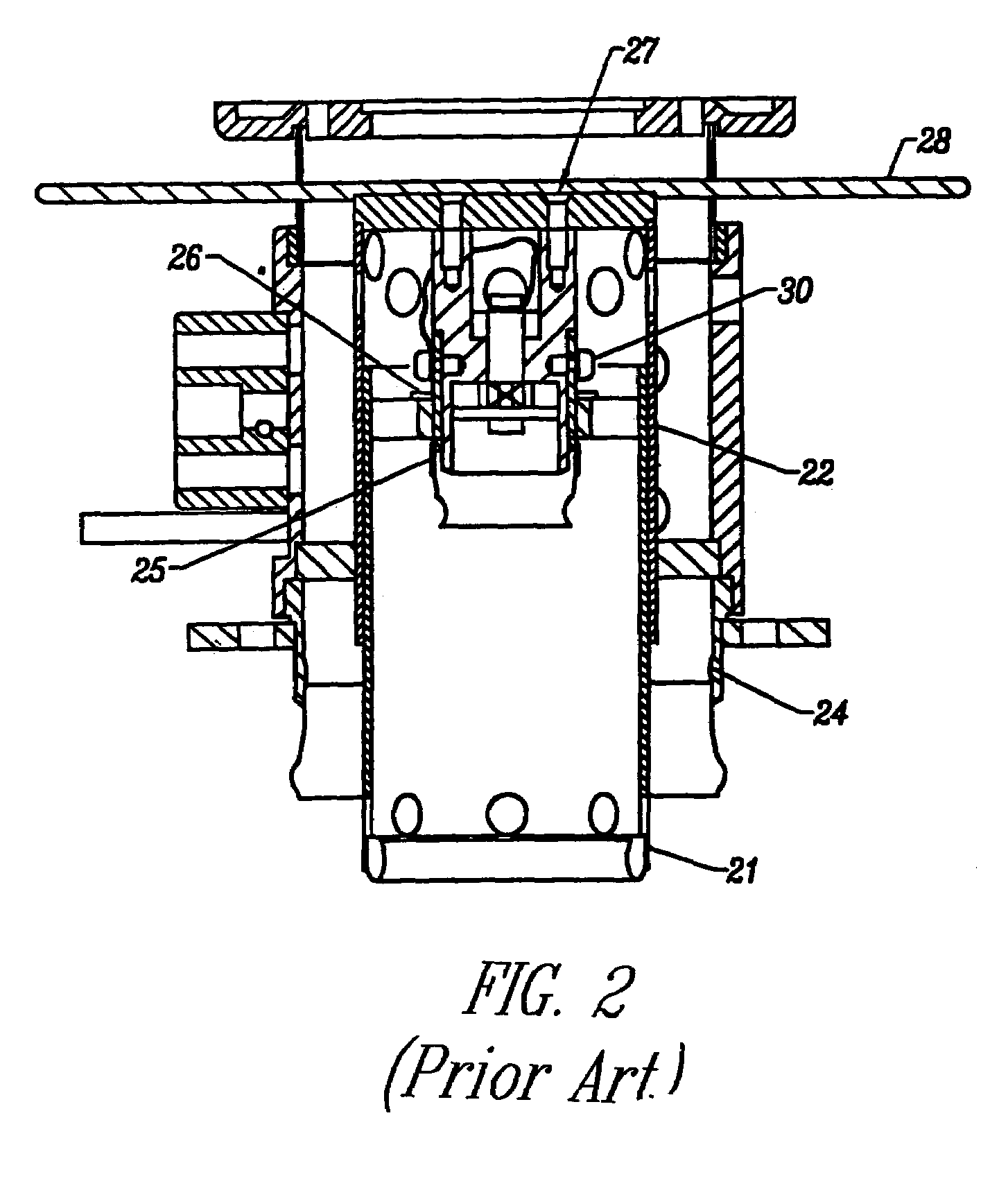
CROSS-REFERENCES[0001]The present application claims the benefit of U.S. Provisional Patent Application Ser. No. 60 / 180,798, filed Feb. 7, 2000 in the names of Wilson W. Toy, Christopher Yates, Paul Krzeminski, Robert N. Tomoe, Edmund T. Davis and assigned to Communication and Power Industries, a Delaware Corporation.BACKGROUND OF THE INVENTION[0002]1. Field of the Invention[0003]The present invention relates to vacuum electron devices (VEDs). More particularly, the present invention relates to input circuits for high power RF amplifiers which employ VEDs such as Klystrodes, Inductive Output Tubes (IOTs), and the like in the television broadcast service.[0004]2. The Background Art[0005]Vacuum tube amplifiers generally include an input circuit having three major components: the enclosure, the input resonator, and the socket. The enclosure houses the socket and the input resonator to which high voltage connections are made. Not only does the enclosure envelope the circuit, but its fun...

Claims


Application Information

Patent Timeline
Patent Type & Authority Patents(United States)
IPC IPC(8): H01R13/44H01J23/14E05D15/40H01J23/12H03F3/54
CPCH01J23/12E05D15/40Y10S439/911
Inventor TOY, WILSON WAIYATES, CHRISTOPHER PAULKRZEMINSKI, PAUL ALLENTORNOE, ROBERT N.DAVIES, EDMUND THOMAS
Owner COMM & POWER IND
Learn More