
Speckle reduction method and apparatus

a technology of speckle reduction and speckle, applied in the direction of optical radiation measurement, radiation control device, luminescent dosimeter, etc., can solve the problem of particularly problematic speckl

Inactive Publication Date: 2006-04-18
ALIGN TECH
View PDF16 Cites 77 Cited by
  • Summary
  • Abstract
  • Description
  • Claims
  • Application Information

AI Technical Summary

Benefits of technology

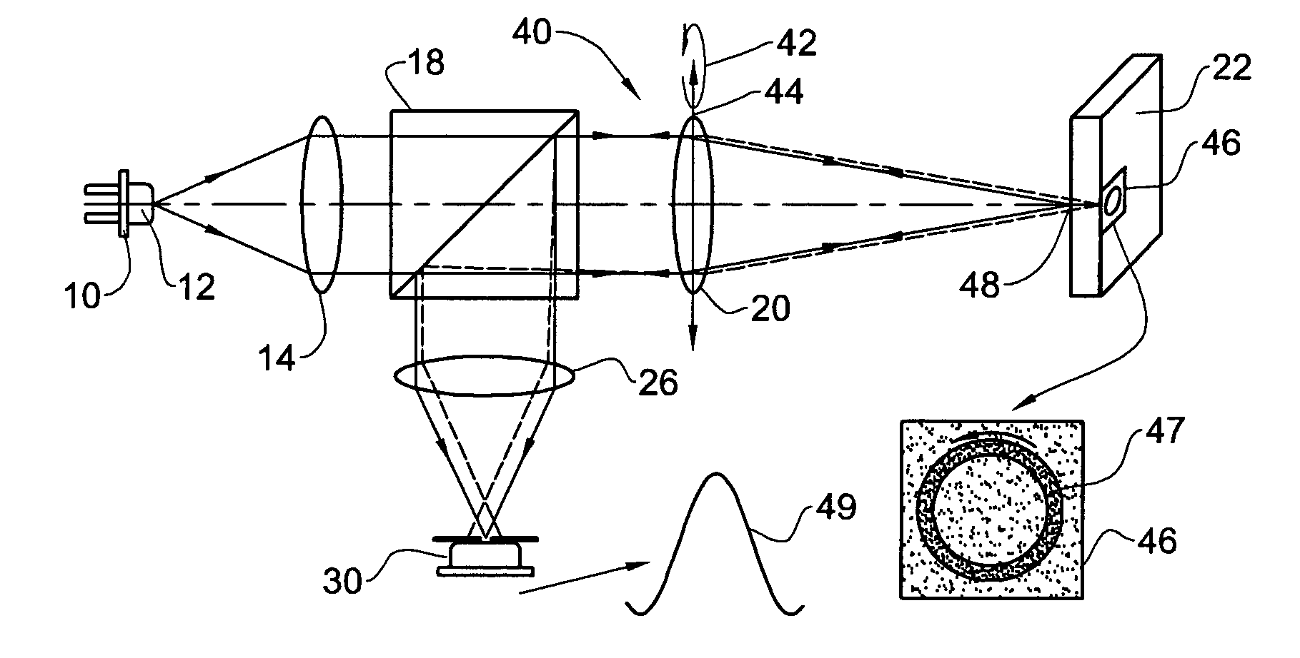
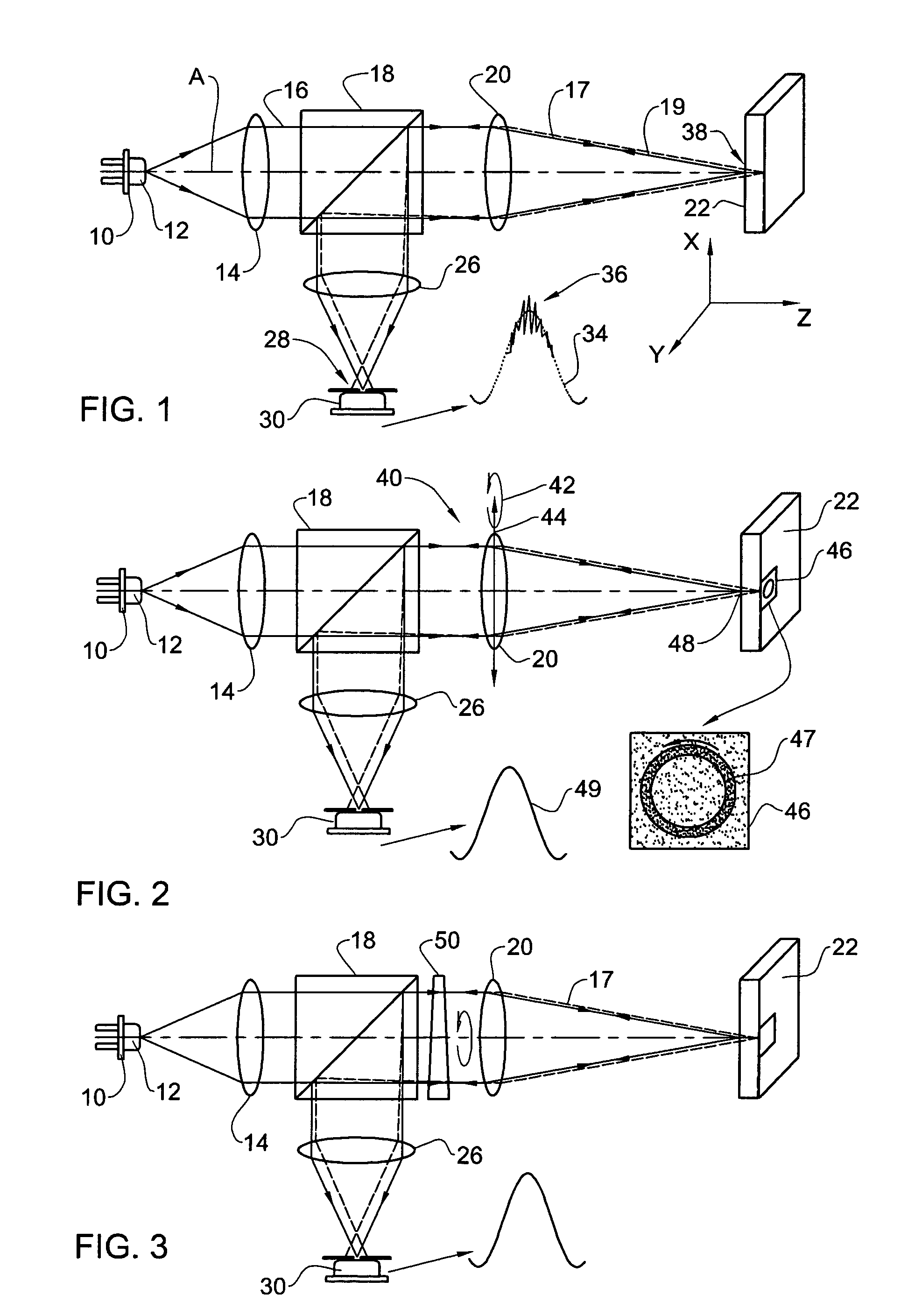
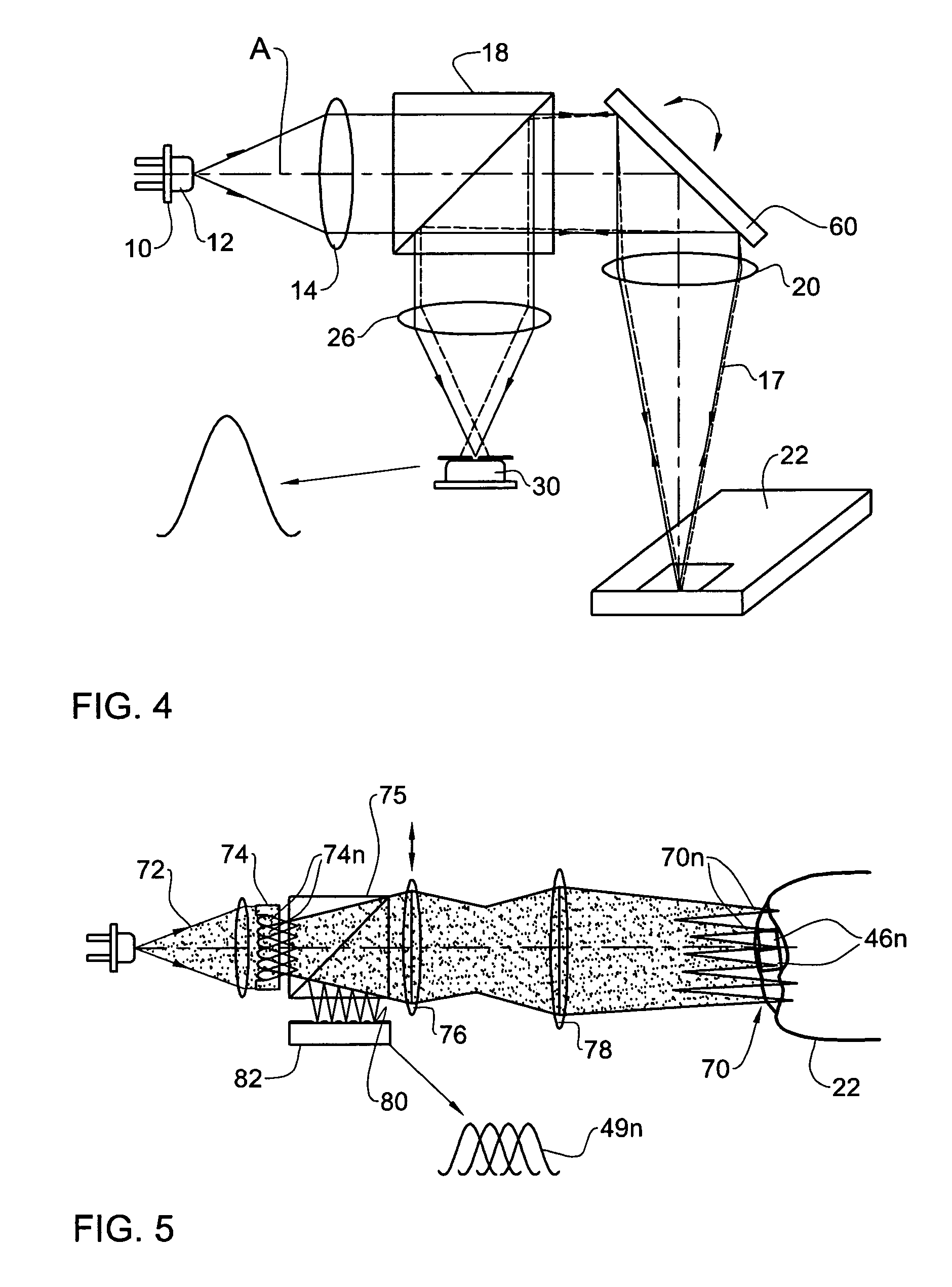
The present invention provides a method and apparatus for reducing speckle in an imaging system using coherent light. The apparatus includes a confocal aperture and means for focusing an incident beam on a specimen surface. A detector receives and detects light reflected from the surface. The detector has an integration time, and an optical component moves the focused spot to a number of distinct locations in a plane perpendicular to the optical axis within the detector's integration time. The movement of the optical component ensures that the detector does not feel the movement, resulting in a static image. The speckle reduction technique involves obtaining a number of independent speckle configurations corresponding to the number of distinct locations of the spot, which are averaged by the detector over its integration time. The invention can be applied equally well to multi-spot confocal systems.

Problems solved by technology

In such imaging, also known as confocal microscopy, speckle is particularly problematic because the confocal imaging process requires focusing laser light on the specimen surface when the most speckle occurs.

Method used


Image

  • Speckle reduction method and apparatus
  • Speckle reduction method and apparatus
  • Speckle reduction method and apparatus

Examples


Embodiment Construction

[0030]FIG. 1 shows a typical apparatus for determining a 3-D profile, or topography, of the surface of an object / specimen, e.g. a tooth, at a desired lateral and axial resolution. The apparatus is a confocal imaging system comprising a laser 10, which constitutes a source of coherent light 12; a collimating lens 14 disposed in front of the laser for collimating the emitted light into a beam 16; a beam splitter 18 through which the collimated beam 16 passes; an optical imaging component in the form of an objective lens 20 for focusing the light beam into a beam 17 (hereinafter ‘incident light beam’), on a non-flat specimen 22 whose topography is to be determined. The above components are disposed along an optical axis A. The specimen 22 is shown in a perspective view to emphasize that it contains a depth (in Z-direction coinciding with the optical axis A) as well as a length and a width (in an X-Y plane perpendicular to the optical axis A). The incident light beam 17 that illuminates...


PUM


Abstract

An apparatus adapted for confocal imaging of a non-flat specimen comprising a coherent light source for producing a light beam, imaging optics adapted to focus the light beam into at least one spot on a surface of a specimen, and a detector adapted to receive and detect light reflected from the specimen surface. The imaging optics comprise at least one optical component located so that the light reflected from the specimen surface passes therethrough on its way to the detector. The optical component is movable so as to move the at least one spot, within a range of movement, to a number of distinct locations in a plane perpendicular to the apparatus' optical axis, within the detector's integration time.

Description

FIELD OF THE INVENTION[0001]This invention relates to the reduction of speckle noise in optical systems comprising imaging optics, in which a coherent light source is used.BACKGROUND OF THE INVENTION[0002]A common difficulty associated with the use of coherent light sources such as lasers in imaging optical systems is a phenomenon known as speckle. Speckle arises when coherent light scattered from a rough surface is detected by an intensity detector that has a finite aperture, such as an observer's eye or a detector. The image on the screen appears to be quantized into little areas with sizes equal to the detector resolution spot. The detected spot intensity varies randomly from darkest, if contributions of the scattering points inside the spot interfere destructively, to brightest if they interfere constructively. This spot-to-spot intensity fluctuation is referred to as speckle. The resultant speckled light signal on the detector appears as spatial and temporal noise in whatever s...

Claims


Application Information

Patent Timeline
Patent Type & Authority Patents(United States)
IPC IPC(8): G01J1/00A61B6/00G02B21/00G02B27/48G03H1/32
CPCG02B21/0056G02B21/006G01J1/0448G02B27/48G03H1/32G02B21/008
Inventor BABAYOFF, NOAMATIYA, YOSSEFPHILIPP, TZVI
Owner ALIGN TECH
Learn More