Touch switch with integral control circuit

a control circuit and touch switch technology, applied in the field of touch switch, can solve the problems of unsatisfactory known touch switch design, circuits which are often complicated and remote from the touch pad, and unintended switch actuation, and achieve the effect of preventing unintended switch actuation

Inactive Publication Date: 2006-04-18
TOUCHSENSOR TECH
View PDF13 Cites 97 Cited by
  • Summary
  • Abstract
  • Description
  • Claims
  • Application Information

AI Technical Summary

Benefits of technology

[0016]It is an object of the invention to provide a reliable touch switch apparatus which is substantially unaffected by the presence of contaminants, electrical interference, and other disturbances proximate the touch switch and its associated control circuitry so as to prevent unintended switch actuation when the touch switch is affected by such disturbances.

Problems solved by technology

These penetrations, as well as penetrations in the switch itself, can allow dirt, water and other contaminants to pass through the substrate or become trapped within the switch, thus leading to electrical shorts and other malfunctions.
The touch pads communicate with control or interface circuits which are often complicated and remote from the touch pads.
Although touch switches solve many problems associated with mechanical switches, known touch switch designs are not perfect.
For example, many known touch switches can malfunction when contaminants such as water or other liquids are present on the substrate.
The contaminant can act as a conductor for the electric fields created about the touch pads, causing unintended switch actuations.
This presents a problem in areas where such contaminants are commonly found, such as a kitchen and some factory environments.
Existing touch switch designs can also suffer from problems associated with crosstalk, i.e., interference between the electric fields about adjacent touch pads.
Crosstalk can cause the wrong touch switch to be actuated or can cause two switches to be actuated simultaneously by a touch proximate a single touch pad.
Many known touch switch designs are also susceptible to unintended actuations due to electrical noise or other interferences affecting a touch pad itself, or the leads extending from the touch pad to its associated control circuit.
Existing touch switch designs commonly require complicated control circuits in order to interface with the devices they control.
These control circuits are likely to be comprised of a large number of discrete components which occupy considerable space on a circuit board.
The size and remoteness also complicate the overall touch switch panel design, resulting in increased production cost and complexity.
Certain apparatus utilizing conventional mechanical switches do not require, and may not readily accommodate, such grounding leads.
Adapting such apparatus for use with such touch switches can require the addition of special grounding provisions, thus increasing design and production time, complexity, and cost.
These ground lead requirements can preclude simple, direct replacement of conventional mechanical switch panels with touch switch panels.
Even though this approach has several advantages over the prior art, there are some attributes that may limit its application.
However, this technique may require the use of additional circuitry to interface with the controlled device, thus increasing cost and complexity to the overall touch switch design.
Also, even though the low impedance approach of this technique can differentiate between contaminants with some finite amount of impedance and a human touch with some finite amount of impedance, this technique may not be enough to differentiate between extremely low levels of impedance.
A common mode disturbance, such as a contaminant substantially covering both electrodes, is likely to affect the electric field about each of the electrodes substantially equally.
Although the differential measuring circuit approach addresses many problems known in the prior art, it is relatively complex and can be costly to design and manufacture.
The additional parts are likely to take up more space on a touch switch panel.
As such, the control circuit is likely to be even farther from the touch pad than it might be with a non-differential circuit design, requiring long leads between the touch pad and its control circuit.
Proper component matching presents an additional manufacturing burden and is likely to add cost.

Method used


Image

  • Touch switch with integral control circuit
  • Touch switch with integral control circuit
  • Touch switch with integral control circuit

Examples


Embodiment Construction

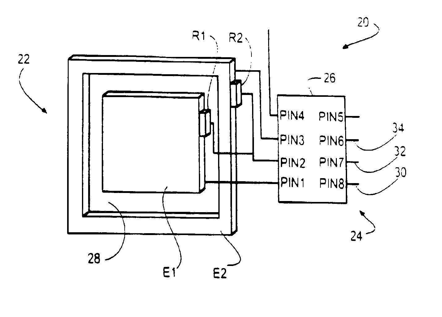
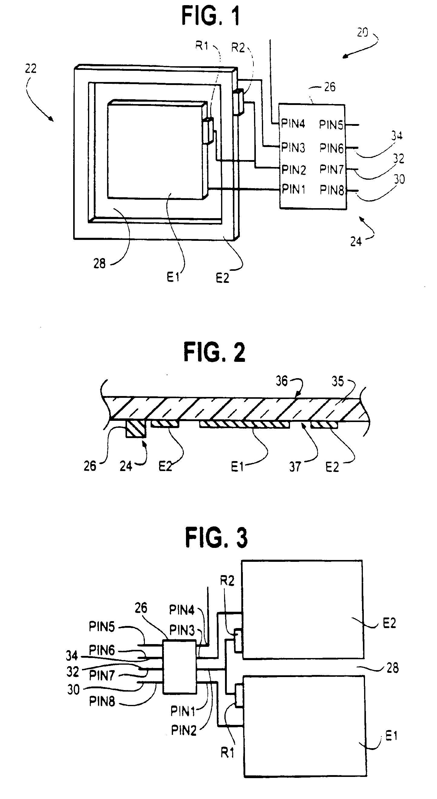
[0042]The invention pertains to a touch switch apparatus comprising a touch pad having one or more electrodes and a control circuit. Many of the drawing figures illustrating the control circuit depict the circuit as large in relation to the touch pad, for clarity. In typical applications, however, the control circuit may be small compared to the touch pad, and is preferably in the form of one or more integrated circuit chips.

[0043]FIG. 1 is a perspective representation of one preferred embodiment of a touch switch apparatus 20 of the present invention. Touch switch apparatus 20 comprises a touch pad 22, a control circuit 24 comprising an integrated circuit (IC) chip 26 having eight output terminals PIN1-PIN8, and first and second resistors R1 and R2. In the embodiment shown, touch pad 22 comprises a first electrode E1 and a second electrode E2, although the touch pad may also be comprised of more or fewer than two electrodes. Although control circuit 24 could be fabricated using dis...


PUM


Abstract

A touch switch apparatus for detecting the presence of an object such as a human appendage, the apparatus having a touch pad and a local control circuit connected to the touch pad and to a controlled device. The touch pad preferable includes a first electrode and a second electrode spaced from and surrounding the first electrode. The control circuit is preferably in integrated circuit form. A signal is provided to the touch pad to generate an electric field thereabout. Introduction of a stimulus near the touch pad disturbs the electric field. The control circuit detects the electric field disturbance in and generates a control signal in response.

Description

CROSS REFERENCE TO RELATED APPLICATIONS[0001]This application is a continuation of, and claims priority from, application Ser. No. 10 / 027,884 filed on Oct. 25, 2001 now U.S. Pat. No. 6,713,897 which is a continuation of application Ser. No. 09 / 234,150 filed on Jan. 19, 1999 (now U.S. Pat. No. 6,320,282).FIELD OF THE INVENTION[0002]The present invention relates to touch panel systems and, more particularly, to touch switches (i.e., switches that are operated, for example, by touching a finger to or about a touch pad) and related control circuits for use as replacements for mechanical switches.BACKGROUND OF THE INVENTION[0003]Mechanical switches have long been used to control apparatus of all types, including household appliances, machine tools, and other domestic and industrial equipment. Mechanical switches are typically mounted on a substrate and require some type of penetration through the substrate. These penetrations, as well as penetrations in the switch itself, can allow dirt,...

Claims


Application Information

Patent Timeline
Patent Type & Authority Patents(United States)
IPC IPC(8): H01H35/00G06F3/02H03K17/96
CPCH03K17/962H03K2217/96077H03K17/9622
Inventor CALDWELL, DAVID W.
Owner TOUCHSENSOR TECH
Why Eureka
Try Eureka