
Methods and system suppressing clutter in a gain-block, radar-responsive tag system

a gain-block and tag system technology, applied in the field of radar-responsive tag systems, can solve the problems of clutter, interference with the ability of radar, passive echoes, etc., and achieve the effect of easy suppression of clutter

Inactive Publication Date: 2006-04-18
NAT TECH & ENG SOLUTIONS OF SANDIA LLC
View PDF8 Cites 52 Cited by
  • Summary
  • Abstract
  • Description
  • Claims
  • Application Information

AI Technical Summary

Benefits of technology

The present invention provides a method for clutter suppression in radar systems by applying a new modulation to each tag echo pulse and using a reversed-chirp de-ramp pulse to correctly process the tag echoes. This allows for easy clutter suppression on each tag echo pulse processed by the radar system. The invention also includes a system for communicating between radar and tag devices, a method for suppressing clutter during communication, and a program product for implementing the invention. The technical effects of the invention include improved radar performance and reliable communication between radar and tag devices.

Problems solved by technology

Because echoes from passive terrain also return to the radar at about this same center frequency and at about the same time as the tag's echo, the passive echoes can interfere with the radar's ability to detect the tag and decode data up-linked from the tag.
Passive terrain echoes can be referred to as clutter due to the fact that they are not desirable and serve only to reduce our ability to process the desired echoes coming from the tag.
That is, the aforementioned method does not achieve any clutter suppression on a single pulse.

Method used


Image

  • Methods and system suppressing clutter in a gain-block, radar-responsive tag system
  • Methods and system suppressing clutter in a gain-block, radar-responsive tag system
  • Methods and system suppressing clutter in a gain-block, radar-responsive tag system

Examples


Embodiment Construction

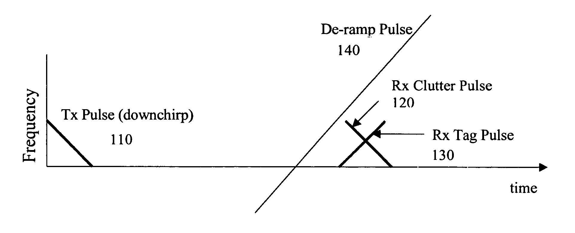
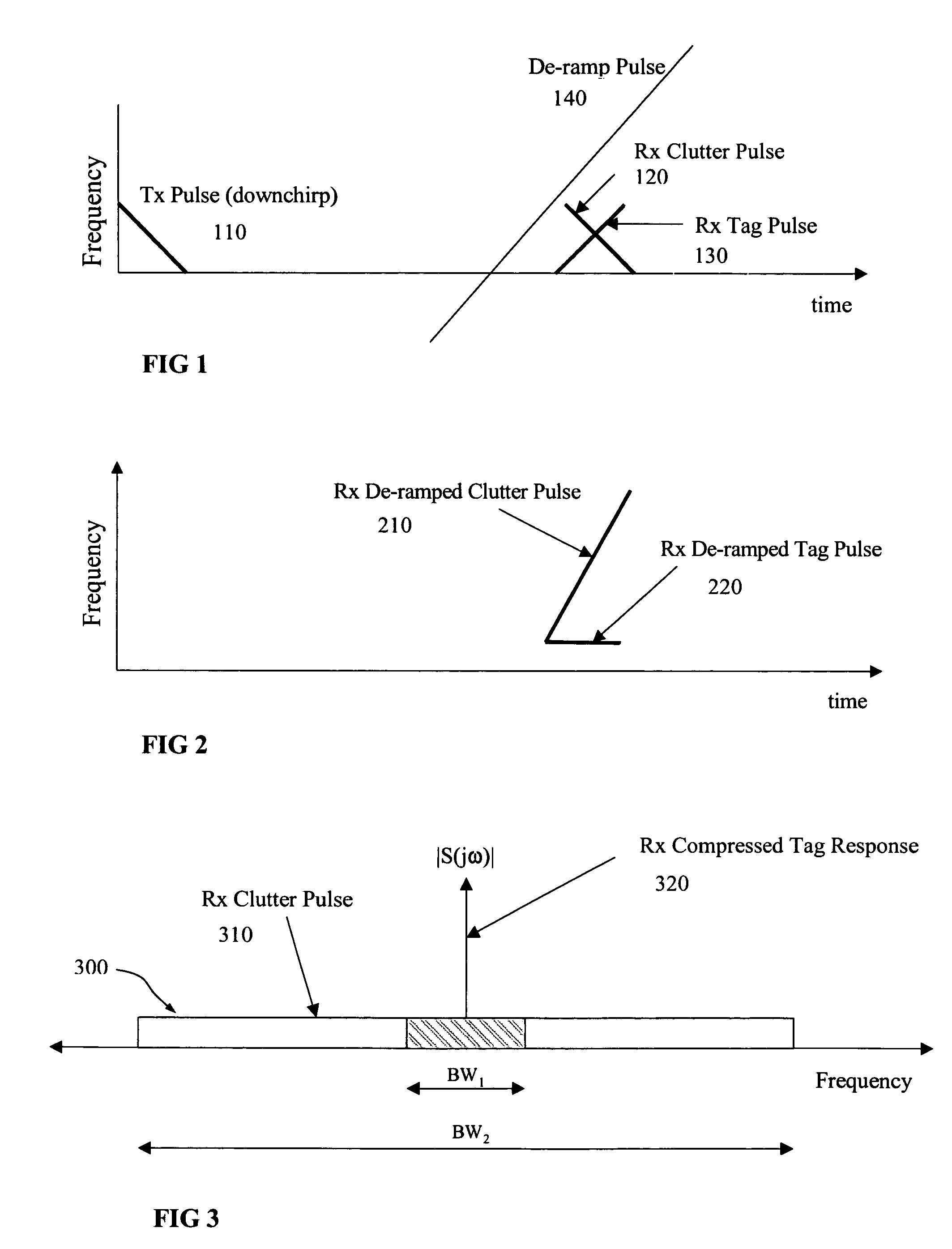
[0028]The new modulation disclosed herein is a specific form of intrapulse modulation—the internal characteristics of each separate echo pulse are modified by the tag. The modulation method of the original, aforementioned '830 patent only changed the electrical phase of each echo pulse by a constant amount. The method of the present invention modifies each tag echo pulse by reversing the direction of the linear frequency modulation originally imparted to the radar pulse by the radar prior to transmission of that same pulse. In order to correctly process the tag's echo, the radar processes the tag's echo using a reversed linear frequency ‘de-ramp’ reference pulse.

[0029]What is described in detail herein is a new method of obtaining clutter suppression with an in-band tag system. The present invention achieves approximately 15 dB of clutter suppression on each and every tag echo pulse returned to the radar. The Reverse-Chirp Algorithm that is herein presented applies to radars that tr...


PUM


Abstract

Methods and systems reduce clutter interference in a radar-responsive tag system. A radar transmits a series of linear-frequency-modulated pulses and receives echo pulses from nearby terrain and from radar-responsive tags that may be in the imaged scene. Tags in the vicinity of the radar are activated by the radar's pulses. The tags receive and remodulate the radar pulses. Tag processing reverses the direction, in time, of the received waveform's linear frequency modulation. The tag retransmits the remodulated pulses. The radar uses a reversed-chirp de-ramp pulse to process the tag's echo. The invention applies to radar systems compatible with coherent gain-block tags. The invention provides a marked reduction in the strength of residual clutter echoes on each and every echo pulse received by the radar. SAR receiver processing effectively whitens passive-clutter signatures across the range dimension. Clutter suppression of approximately 14 dB is achievable for a typical radar system.

Description

STATEMENT OF GOVERNMENT INTEREST[0001]The U.S. Government has rights in this invention pursuant to Contract DE-AC04-94AL85000 between Sandia Corporation and the U.S. Department of Energy.FIELD OF THE INVENTION[0002]The present invention is generally related to radar-responsive tag systems. More particularly, the present invention is related to methods of achieving clutter suppression on each and every tag echo pulse processed by a radar system.BACKGROUND[0003]U.S. Pat. No. 6,577,266, issued Jun. 10, 2003 to Axline et al entitled “Transponder Data Processing Methods and Systems,” and U.S. Pat. No. 5,486,830, issued Jan. 23, 1996 to Axline entitled “Radar Transponder Apparatus and Signal Processing Technique,” provide background for an in-band tag system and the present invention. These patents are herein incorporated by reference into the current specification for their teachings.[0004]During operation, a tag receives pulses from the radar, modulates and amplifies these pulses, and r...

Claims


Application Information

Patent Timeline
Patent Type & Authority Patents(United States)
IPC IPC(8): G01S13/74
CPCG01S13/76G01S13/282G01S13/90G01S13/9029
Inventor ORMESHER, RICHARD C.AXLINE, ROBERT M.
Owner NAT TECH & ENG SOLUTIONS OF SANDIA LLC
Learn More