
System and method to estimate the location of a receiver in a multi-path environment

Inactive Publication Date: 2006-04-18
CSR TECH INC
View PDF4 Cites 29 Cited by
  • Summary
  • Abstract
  • Description
  • Claims
  • Application Information

AI Technical Summary

Benefits of technology

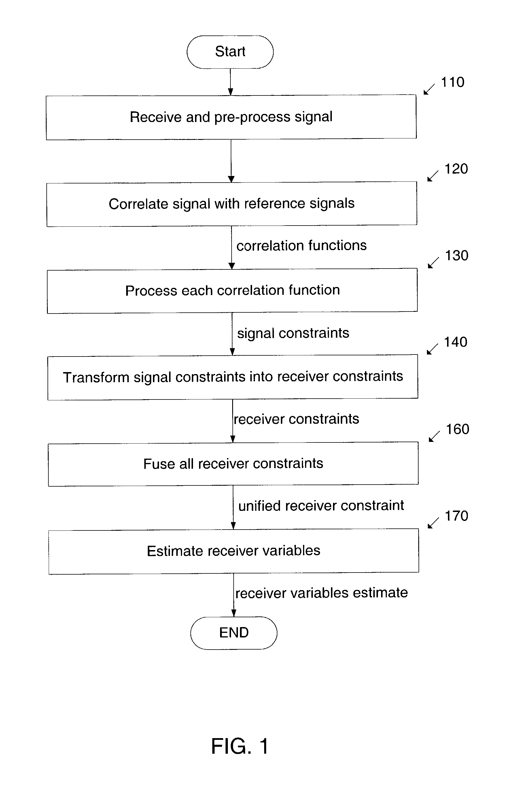
[0006]The present invention overcomes the limitations of previous approaches by incorporating the uncertainty caused by multipath effects into the estimation of the receiver variables. The method is based on representing multipath uncertainty by means of signal constraints and receiver constraints. Embodiments of this method generate, transform, and fuse constraints to obtain a final estimate of the receiver variables in a way that mitigates multipath effects. The term “constraint” encompasses any means or device that conveys uncertain information about one or more variables. Sometimes, the term “uncertainty representation” is used as a synonym of “constraint”. An example of a constraint is a probability density. Another example is an uncertainty region, that is, a subset of the space to which a particular variable or set of variables belong. Such a subset can be described, for instance, by a set of linear inequalities. Another example of a constraint is a collection of probability densities. This type of constraint can be described, for instance, by a parametric probability density whose parameters are constrained to be within certain ranges. Another example is a system of linear equations. Another type of constraint is a “sub-probability” density whose total mass is less than one. The missing mass is associated to an outlier event for which no constraint is provided.

Problems solved by technology

The straightforward least-square triangulation methods that assume straight unaltered propagation paths may perform very poorly in multipath environment.

Method used


Image

  • System and method to estimate the location of a receiver in a multi-path environment
  • System and method to estimate the location of a receiver in a multi-path environment
  • System and method to estimate the location of a receiver in a multi-path environment

Examples


Embodiment Construction

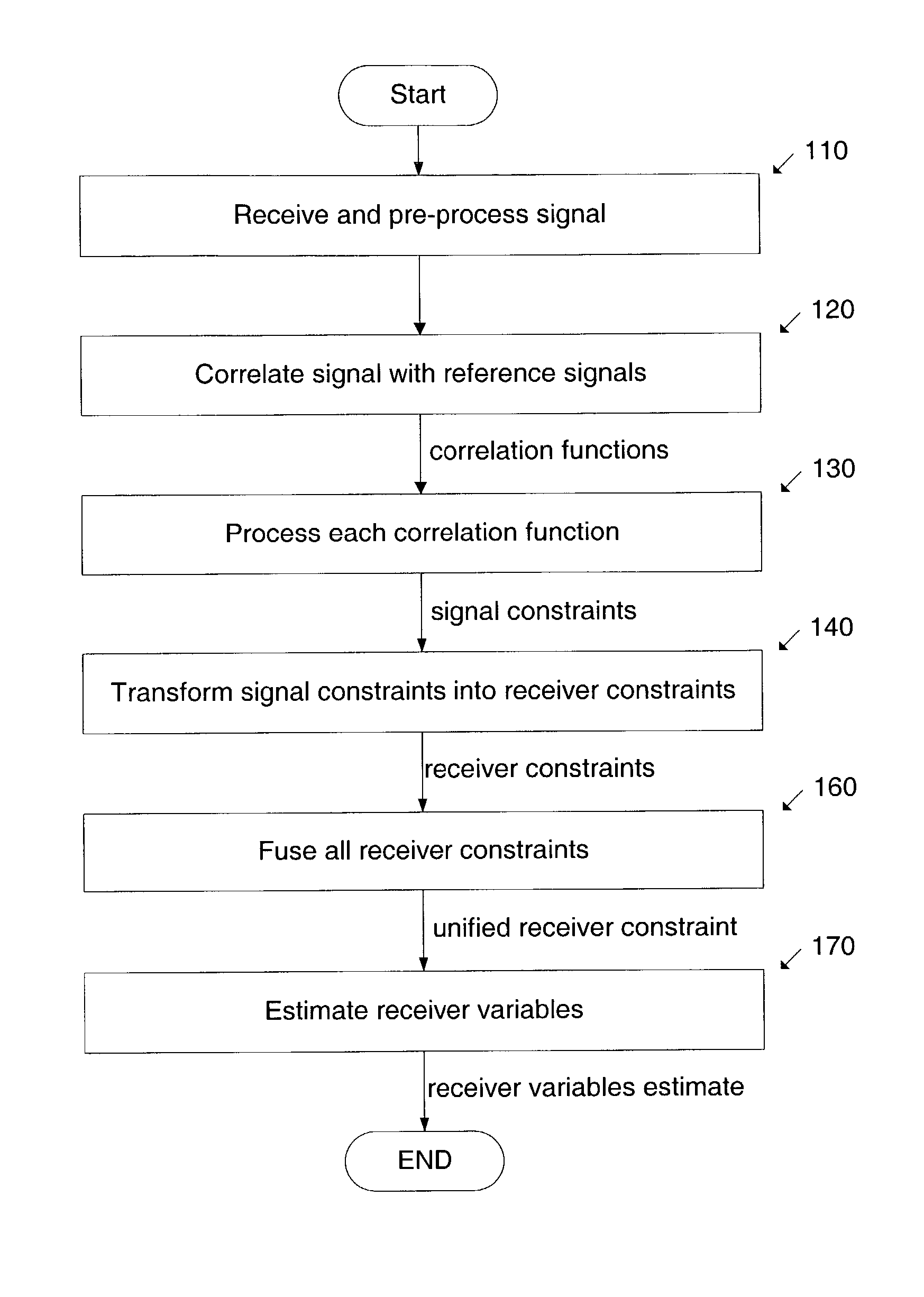
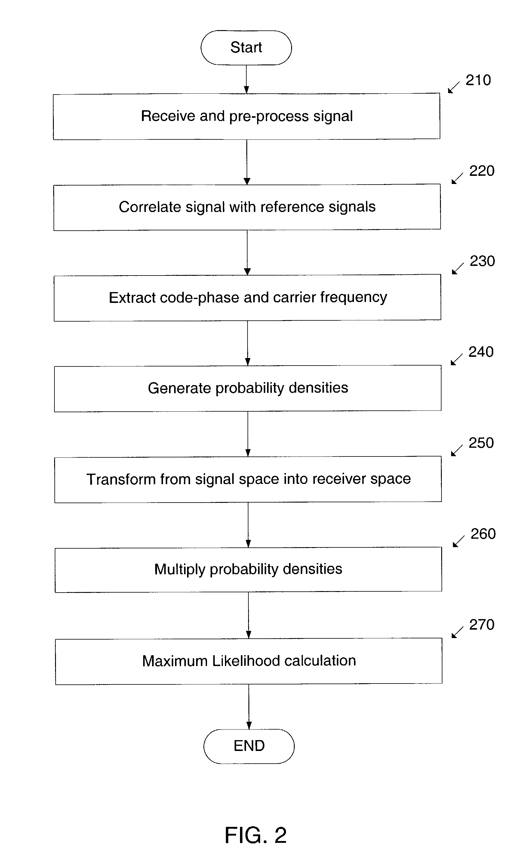
[0046]FIG. 2 and FIG. 3 illustrate a preferred embodiment of the invention.

[0047]At 210 the signal is received and pre-processed in accordance to methods known to those skilled in the art. At 220, the pre-processed signal is correlated with the reference signals associated with each source. Methods to calculate these correlations are described in Application E102.

[0048]At 230, the correlation functions are processed to extract a code-phase value and Doppler frequency value. In some embodiments, this is performed by calculating the ambiguity function:

Ai(τ,f)=Ii2(τ,f)+Qi2(τ,f)  (7)

and by searching for the largest peak of Ai(τ, f). The location of this peak is denoted ({circumflex over (τ)}i,{circumflex over (f)}i):

[0049](τ^i,f^i)=arg⁢⁢maxτ,f⁢⁢Ai⁡(τ,f).(8)

Only peaks above a sensitivity threshold are considered to be valid, hence not all sources processed yield a code-phase value. Those that do are said to have been “acquired”. A method for performing this step efficiently is described ...


PUM


Abstract

System and method to determine the location of a receiver in a multipath environment are provided. The received signal is correlated with the reference signals associated with the transmitting sources. Each correlation function is processed to derive various types of signal constraints, such as probability densities and uncertainty regions or intervals. In some embodiments, these constraints are for the code-phases and the Doppler frequencies. These signal constraints are transformed into constraints on the receiver variables and then fused together into a unified receiver constraint. A-priori constraints, such as constraints on the location of the receiver or the timestamp, may be incorporated into the unified receiver constraint. Some embodiments estimate a location based also on the estimated Doppler frequency. The constraints used by the invention are based on models of multipath effects and are geared towards mitigating these effects. In one of these models, a probability density for code-phase is obtained by convolving a gaussian distribution with an exponential distribution that describes the extra delay introduced by multipath. Another approach is based on identifying outliers in the set of code-phases. In other approaches, uncertainty region constraints and probability densities are combined. The present invention achieves faster and more sensitive signal acquisition and higher location accuracy in multipath environment, without compromising performance in other environments.

Description

CROSS REFERENCE TO RELATED APPLICATIONS[0001]This application claims the benefit of U.S. Provisional Patent Application No. 60 / 318,216, filed Sep. 7, 2001, entitled “Estimation of Receiver Location and Other Parameters in Multipath Environments”.FIELD OF THE INVENTION[0002]The present invention relates to signal processing and, more particularly, to techniques for estimating the location and other variables of a receiver in a multipath environment by processing a signal that contains location-determining signals transmitted by a set of sources.BACKGROUND OF THE INVENTION[0003]Some position determining systems determine certain receiver variables, such as location, velocity and certain parameters of the receiver's clock, by receiving and processing a signal containing location-determining signals transmitted by a plurality of sources. These receiver variables are estimated by first estimating certain signal variables, such as code-phase and Doppler frequency and then by performing a ...

Claims


Application Information

Patent Timeline
IPC IPC(8): G01S3/02G01S19/09G01S1/00G01S5/14G01S11/10G01S19/22G01S19/30G01S19/42G01S19/46G01S19/50G01S19/52
CPCG01S11/10G01S19/22G01S19/52G01S19/42G01S19/50G01S19/30
Inventor STONE, JESSECASADEI, STEFANOMANN, WALLACEVAN ROY, BENJAMIN
Owner CSR TECH INC
Learn More