Image pickup apparatus using a selector circuit

a pickup apparatus and selector circuit technology, applied in the direction of radio frequency control devices, instruments, television systems, etc., can solve the problems of large power consumption, increase in the number of bits of the decoder, and complex circuit structur

Inactive Publication Date: 2006-04-18
CANON KK
View PDF12 Cites 25 Cited by
  • Summary
  • Abstract
  • Description
  • Claims
  • Application Information

AI Technical Summary

Benefits of technology

[0010]Another aspect of the present invention provides a selector circuit comprising: scanning means for sequentially outputting a pulse for selection; first designating means for supplying a start signal for a desired block of a predetermined area divided into a plurality of blocks smaller than a whole ...

Problems solved by technology

The number of pixels of a recent image pickup apparatus using solid state image pickup elements is increasing year after year, and for this reason, the number of bits of a de...

Method used


Image

  • Image pickup apparatus using a selector circuit
  • Image pickup apparatus using a selector circuit
  • Image pickup apparatus using a selector circuit

Examples


first embodiment

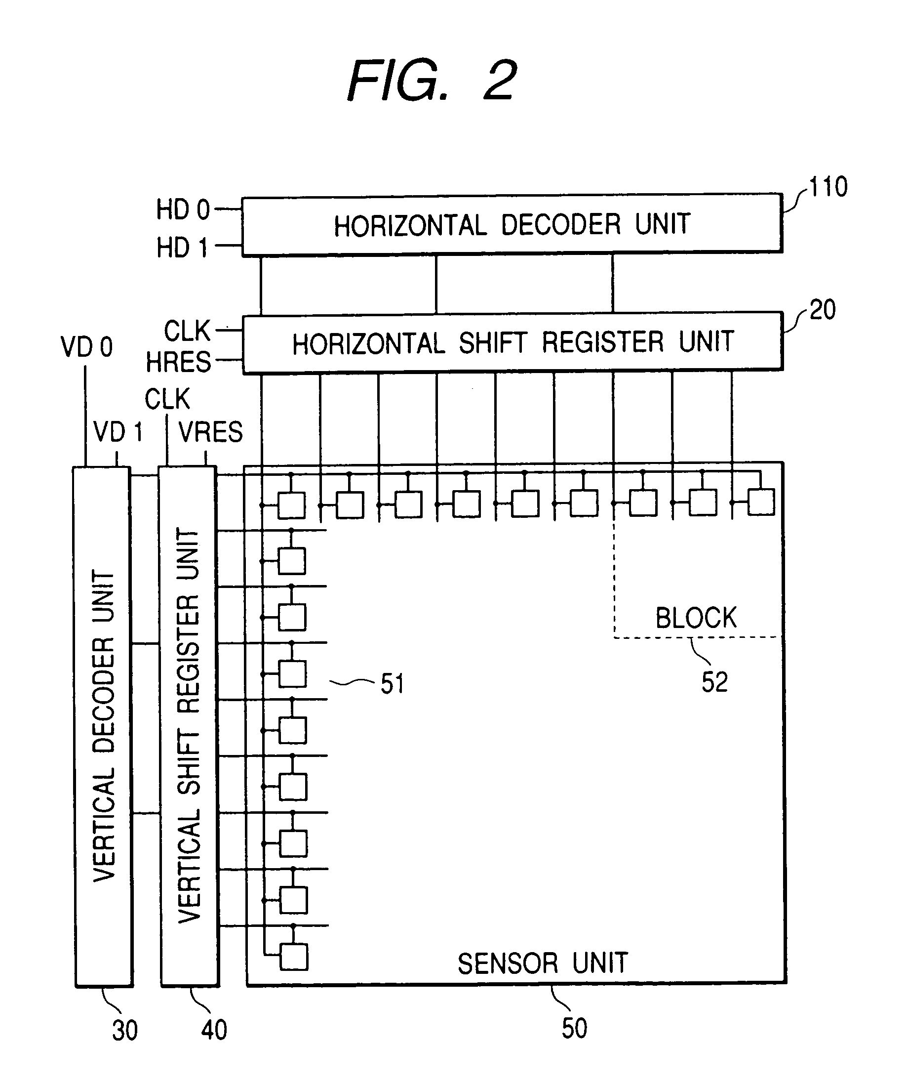
[0030]FIG. 2 shows an example of the configuration of a solid state image pickup apparatus having decoder units and shift register units according to the invention.

[0031]Referring to FIG. 2, a sensor unit 50 has 9×9 pixels. A horizontal shift register unit 20 and a vertical shift register unit 40 are provided to designate each of nine pixels arranged in X- and Y-directions. A horizontal decoder unit 110 and a vertical decoder unit 30 are connected to the horizontal shift register unit 20 and vertical shift resister unit 40, respectively, in order to make the shift register units 20 and 40 designate a desired pixel area. The pixels 51 are divided into blocks 52 each having, for example, 3×3 pixels.

[0032]HD0 and HD1 are input to the horizontal decoder unit 110, and a clock pulse (CLK) and a horizontal reset pulse (HRES) are input to the horizontal shift register unit 20. Similarly, VD0 and VD1 are input the vertical decoder unit 30, and a clock pulse (CLK) and a vertical reset pulse (...


PUM


Abstract

A selector circuit having a shift register for sequentially outputting a select pulse and a decoder circuit for designating a desired block of a plurality of blocks divided from the scan circuit, so as to allow the scan circuit to start to output the select pulse from a head position in the designated desired block.

Description

BACKGROUND OF THE INVENTION[0001]1. Field of the Invention[0002]The present invention relates to a selector circuit for selecting a desired image area of and to an image pickup apparatus using the selector circuit.[0003]2. Related Background Art[0004]With a conventional image sensor having a plurality of solid image pickup elements disposed in a two-dimensional X-Y coordinate plane, each pixel can be directly accessed and a predetermined pixel area can be designated by using horizontal and vertical shift registers for designating X- and Y-addresses and decoder circuits for controlling the horizontal and vertical shift registers.[0005]The number of pixels of a recent image pickup apparatus using solid state image pickup elements is increasing year after year, and for this reason, the number of bits of a decoder increases and the circuit structure becomes complicated. For example, a solid state image pickup device having 2000 pixels in the horizontal line requires a decoder circuit of...

Claims


Application Information

Patent Timeline
IPC IPC(8): H04N3/14H04N5/335G06K9/20H01L27/146H04N1/028H04N5/341H04N5/345H04N5/369H04N5/374H04N5/376H04N5/378
CPCH04N5/361H04N5/3454H04N25/443H04N25/63
Inventor HAYASHI, HIDETOSHIHASHIMOTO, SEIJIYUKI, OSAMUENDO, TOSHIAKI
Owner CANON KK
Why Eureka
Try Eureka