Block distortion detection method, block distortion detection apparatus, block distortion removal method, and block distortion removal apparatus

a technology of block distortion and detection method, which is applied in the direction of instruments, television systems, color signal processing circuits, etc., can solve the problems of block distortion, coding noise, and image quality degradation, so as to reduce the scale of hardware or the like, and improve the accuracy of block distortion detection.

Active Publication Date: 2006-04-18
GK BRIDGE 1
View PDF9 Cites 116 Cited by
  • Summary
  • Abstract
  • Description
  • Claims
  • Application Information

AI Technical Summary

Benefits of technology

[0010]The present invention is made to solve the above-described problems and has for its object to provide a block distortion detection method, a block distortion detection apparatus, a block distortion removal method, and a block distortion removal apparatus, which do not cause degradation in image quality due to false detection when removing block distortion.
[0011]Further, it is another object of the present invention to provide a block distortion detection method, a block distortion detection apparatus, a block distortion removal method, and a block distortion removal apparatus, which can prevent the volume of processing from increasing in proportion to the number of pixels, and which can suppress an increase in the volume of processing even when an image signal has high resolution.

Problems solved by technology

However, since visual characteristics of human beings have lower ability of discrimination for higher frequencies, degradation in image quality due to quantization is less conspicuous as the quantization step used for quantization is smaller.
However, when the bit rate becomes lower, i.e., when the compression ratio is increased, degradation in image quality, i.e., coding noise, begins to be conspicuous.
There is block distortion as typical coding noise in the MPEG scheme.
Block distortion is different from conventional analog noise in that it is considerably conspicuous as degradation in image quality.
However, even when the motion vector is large, degradation in image quality occurs when an area having high-frequency components is subjected to filtering.

Method used


Image

  • Block distortion detection method, block distortion detection apparatus, block distortion removal method, and block distortion removal apparatus
  • Block distortion detection method, block distortion detection apparatus, block distortion removal method, and block distortion removal apparatus
  • Block distortion detection method, block distortion detection apparatus, block distortion removal method, and block distortion removal apparatus

Examples


embodiment 1

[Embodiment 1]

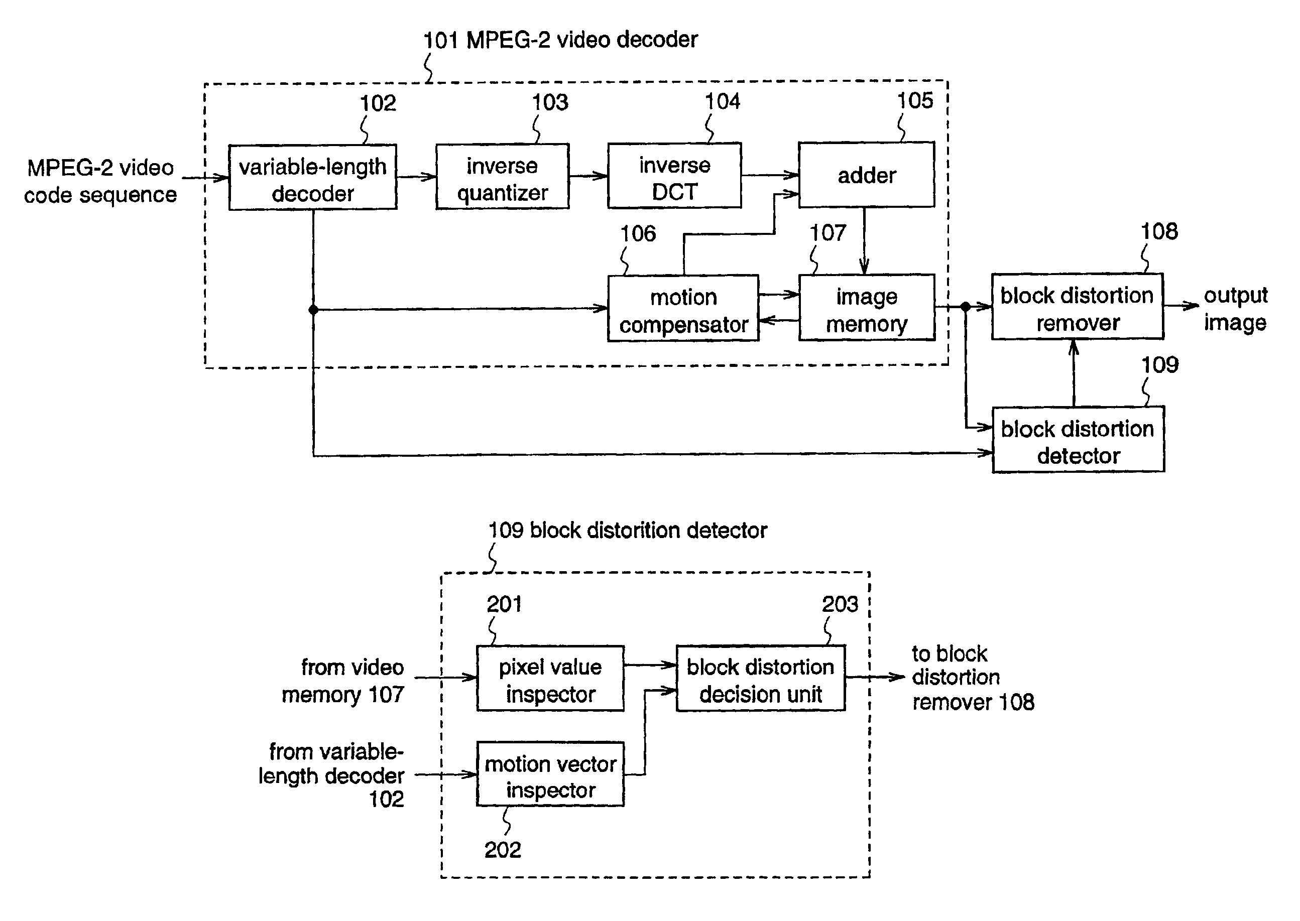
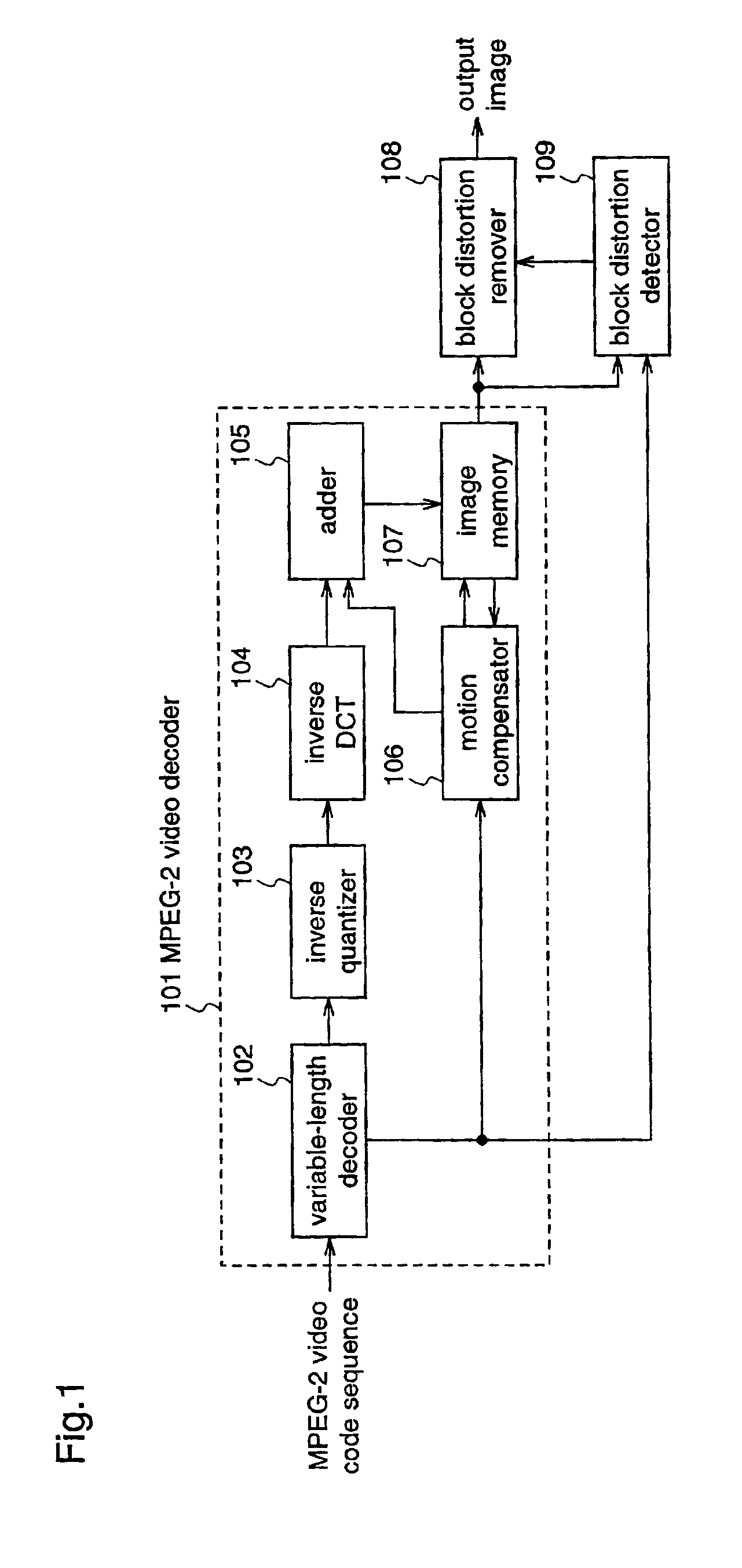
[0050]FIG. 1 is a block diagram illustrating an MPEG-2 decoder having a block distortion detection apparatus and a block distortion removal apparatus which employ a block distortion detection method and a block distortion removal method according to a first embodiment of the invention, respectively. In FIG. 1, 102 denotes a variable-length decoder for decoding an MPEG-2 video code sequence which is a variable-length code; 103 denotes an inverse quantizer for subjecting the decoded variable-length code to inverse quantization; 104 denotes an inverse DCT unit for subjecting the output of the inverse quantizer 103 to inverse DCT; 106 denotes a motion compensator for subjecting the output of the variable-length decoder 102 to motion compensation; 105 denotes an adder for adding the output of the inverse DCT unit 104 and the output of the motion compensator 106; 107 denotes an image memory for temporarily holding decoded image data; and 101 denotes an MPEG-2 video decoder c...

embodiment 2

[Embodiment 2]

[0091]The second embodiment of the present invention is different from the first embodiment in the operation of the block distortion remover 108. Accordingly, only the operation of the block distortion remover 108 according to the second embodiment will be described hereinafter.

[0092]FIG. 9 is a block diagram illustrating the construction of the block distortion remover 108 according to the second embodiment. The block distortion remover 108 comprises a filter unit 501 and a weighted-average calculator 502.

[0093]The block distortion remover 108 receives image data from the image memory 107, and the result of detection of block distortion from the block distortion detector 109. The image data supplied from the image memory 107 is inputted to the filter unit 501 and the weighted-average calculator 502. In the filter unit 501, pixels in the vicinity of all block boundaries are subjected to filtering. For example, the pixels adjacent to each block boundary are subjected to...

embodiment 3

[Embodiment 3]

[0101]FIG. 11 is a block diagram illustrating an MPEG-2 decoder having a block distortion detection apparatus and a block distortion removal apparatus for performing a block distortion detection method and a block distortion removal method according to the third embodiment, respectively. In FIG. 11, a variable-length decoder 102, an inverse quantizer 103, an inverse DCT unit 104, an adder 105, a motion compensator 106, and an image memory 107 are identical to those shown in FIG. 1.

[0102]The MPEG-2 decoder according to the third embodiment further includes a block distortion remover 108, a block distortion detector 709, and a resolution decision unit 710. The resolution decision unit 710 decides a range where the resolution of an MPEG-2 code sequence belongs, by referring to resolution data included in the decoding result of the MPEG-2 code sequence.

[0103]The operations of the variable-length decoder 102, the inverse quantizer 103, the inverse DCT unit 104, the adder 10...


PUM


Abstract

A video decoder is connected with a block distortion detector for specifying the boundary of blocks where block boundary occurs, using decoded image data and information of motion vectors, which are supplied from the video decoder; and a block distortion remover for subjecting pixels in the vicinity of the block boundary of the decoded image to filtering on the basis of the result of detection from the block distortion detector, thereby removing the block distortion. Therefore, block distortion is accurately detected when a compressed and coded image is decoded, and the detected block distortion is removed while minimizing the blurriness of the image.

Description

FIELD OF THE INVENTION[0001]The present invention relates to a method and an apparatus for detecting block distortion which occurs when an image that is subjected to compressive coding in block units is decoded. Further, the invention relates to a method and an apparatus for removing the block distortion.BACKGROUND OF THE INVENTION[0002]In recent years, MPEG (Moving Picture Expert Group), H.263, and the like have been widely used as high-performance compression coding schemes for images in the fields of broadcasting, communication, and storage. In the MPEG or H.263 scheme, coding is carried out by removing redundancies in the spatial direction and in the temporal direction from an image. Hereinafter, the outline of the MPEG scheme will be described.[0003]First of all, in order to remove a redundancy in the spatial direction, which is included in image information, discrete cosine transform (hereinafter referred to as DCT) and quantization are used. To be specific, an input image is ...

Claims


Application Information

Patent Timeline
Patent Type & Authority Patents(United States)
IPC IPC(8): H04N7/12H04N19/00G01R23/09H04N19/102H04N19/117H04N19/136H04N19/139H04N19/167H04N19/189H04N19/196H04N19/423H04N19/44H04N19/503H04N19/513H04N19/80H04N19/86H04N19/91
CPCG01R23/09
Inventor KONDO, SATOSHIITANI, TETSUYA
Owner GK BRIDGE 1
Why Eureka
Try Eureka