Device for cooling coolant in a gas turbine and gas and steam turbine with said device

a technology of coolant cooling and gas turbine, which is applied in the direction of machines/engines, steam generation using hot heat carriers, lighting and heating apparatus, etc., can solve the problems of disproportionately high plant technology expenditure, limited heat transfer of gas turbine coolant into water-steam circuit of assigned steam turbine, and high turbine inlet temperature, etc. problems, to achieve the effect of reliable coolant cooling, high design pressure, and simple design

Active Publication Date: 2006-04-25
SIEMENS AG
View PDF9 Cites 17 Cited by
  • Summary
  • Abstract
  • Description
  • Claims
  • Application Information

AI Technical Summary

Benefits of technology

[0024]The advantages achieved with the invention are in particular that through the embodiment of the coolant cooler as a steam generator for the flow medium in forced throughflow design, the provision of relatively high-quality steam in terms of thermodynamics is made possible during coolant cooling for the gas turbine. Precisely because of its construction as a forced throughflow steam generator, in addition in a relatively simple design, use of the coolant cooler in the supercritical or also in the subcritical pressure range is made possible so that reliable coolant cooling is also guaranteed in modern power plants with high design pressures or in the retrofitting of existing plants using relatively simple means. The coolant cooler is also particularly suited to what is known as solo operation in which no further use is made of the generated steam in an assigned steam turbine plant.
[0025]However, use of the high-quality steam generated in a corresponding pressure stage of the water-steam circuit of a steam turbine is particularly advantageous. Precisely the design as a forced throughflow steam generator makes possible reliable cover of a relatively wide range of operational parameters as a result of the variable evaporation end point. In particular, at temperatures of up to approximately 500° C. produced when using compressor air from the gas turbine as a coolant, when using heat-resisting materials such as, for example, high-temperature steels like 13 Cro Mo 44 or 15 Mo 3, a risk of overheating can be almost ruled out in all operating states. In particular, therefore, it is not necessary to feed the evaporator tubes with a minimum quantity of flow medium. Thereby, precisely in the case of the embodiment of the coolant cooler as a steam generator according to the forced throughflow principle, start-up or light-load operation with dry or partially filled evaporator heating surfaces is possible without the need for a relatively expensive separator vessel between individual pressure stages of the evaporator tubes.
[0026]The design of the coolant cooler as a forced throughflow steam generator therefore also makes it possible to influence the coolant temperature for the gas turbine immediately after start-up of the plant. As a result of the option of starting the coolant cooler with “dry” evaporator tubes, immediately after starting the gas turbine there are no substantial water masses to be heated in the coolant cooler, so that also when starting the gas turbine there is no risk of unintentionally intense cooling of the gas turbine cooling air which might in particular lead to cooling below the dewpoint of the water vapor incorporated in the cooling air with subsequent condensation.

Problems solved by technology

To increase the performance of the gas turbine and thus to achieve the highest possible degree of efficiency, efforts are made to achieve a particularly high temperature of the working substance on the inlet side of the turbine of e.g. 1200° C. to 1500° C. However, such a high turbine inlet temperature may entail material problems, in particular in relation to the heat resistance of the turbine blades and vanes.
With regard to this design objective, the results achieved to date for the transfer of heat produced during the cooling of the coolant of the gas turbine into the water-steam circuit of an assigned steam turbine have been only limited.
However, as has emerged, though slightly increased efficiency with regard to the use of heat produced during cooling of the coolant of the gas turbine is attainable in the case of such a solution, there is disproportionately high expenditure on plant technology.

Method used


Image

  • Device for cooling coolant in a gas turbine and gas and steam turbine with said device
  • Device for cooling coolant in a gas turbine and gas and steam turbine with said device
  • Device for cooling coolant in a gas turbine and gas and steam turbine with said device

Examples


Embodiment Construction

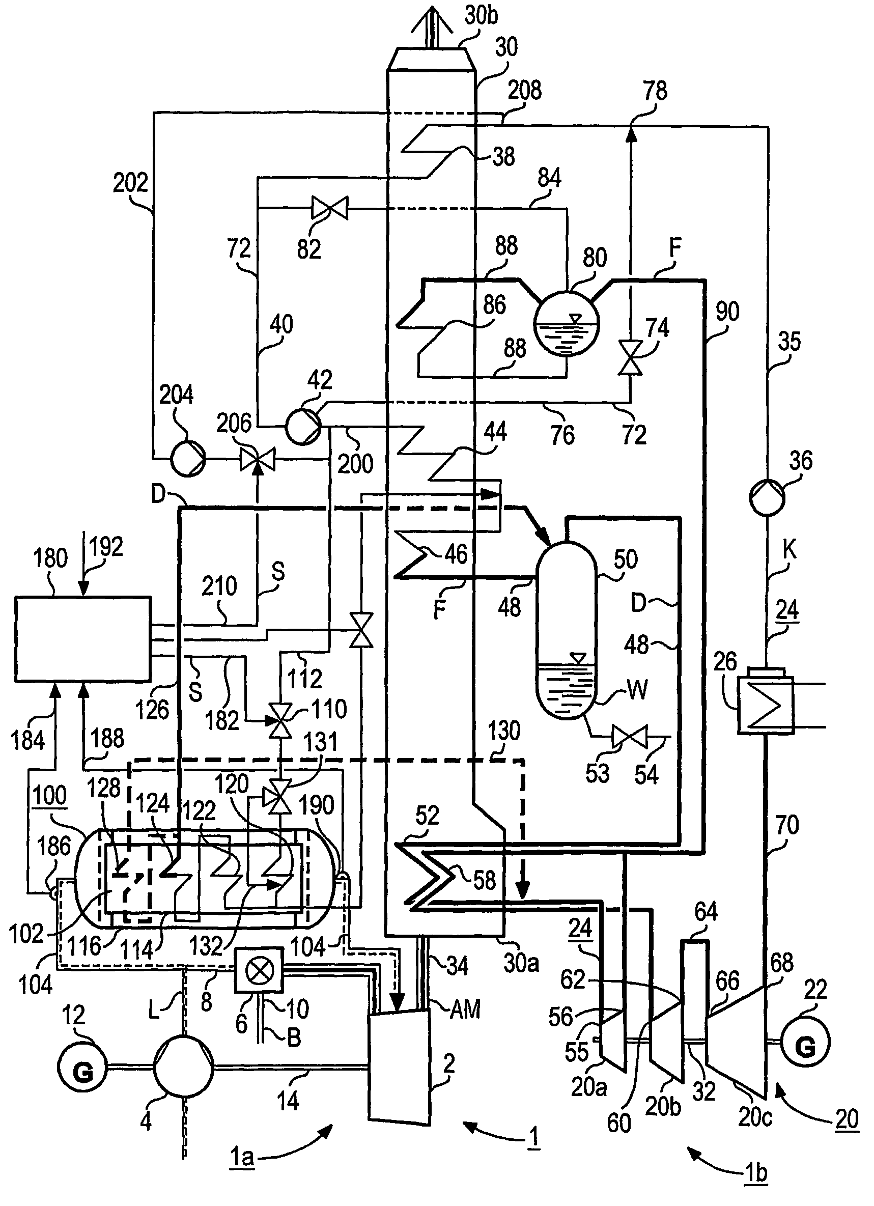
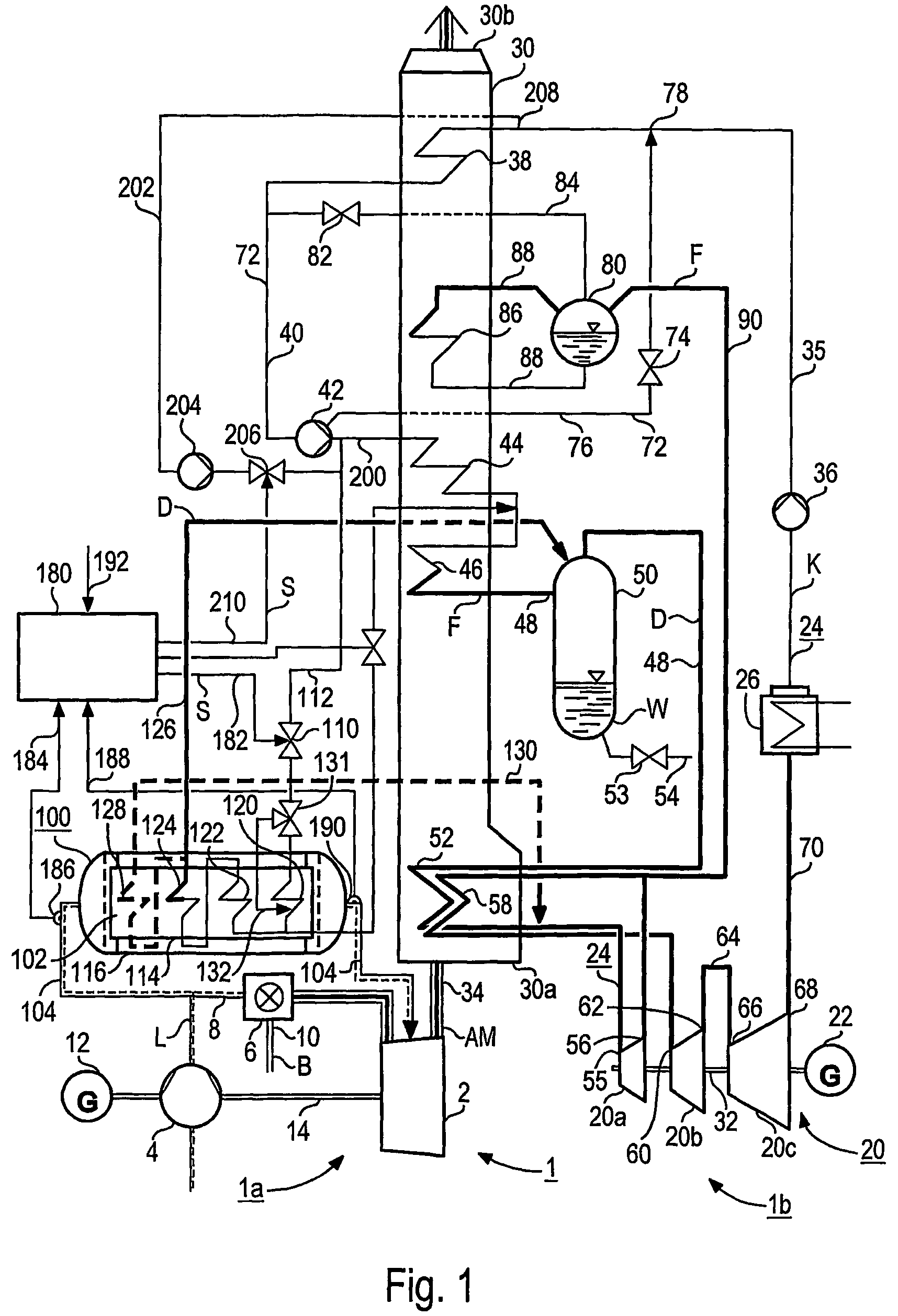
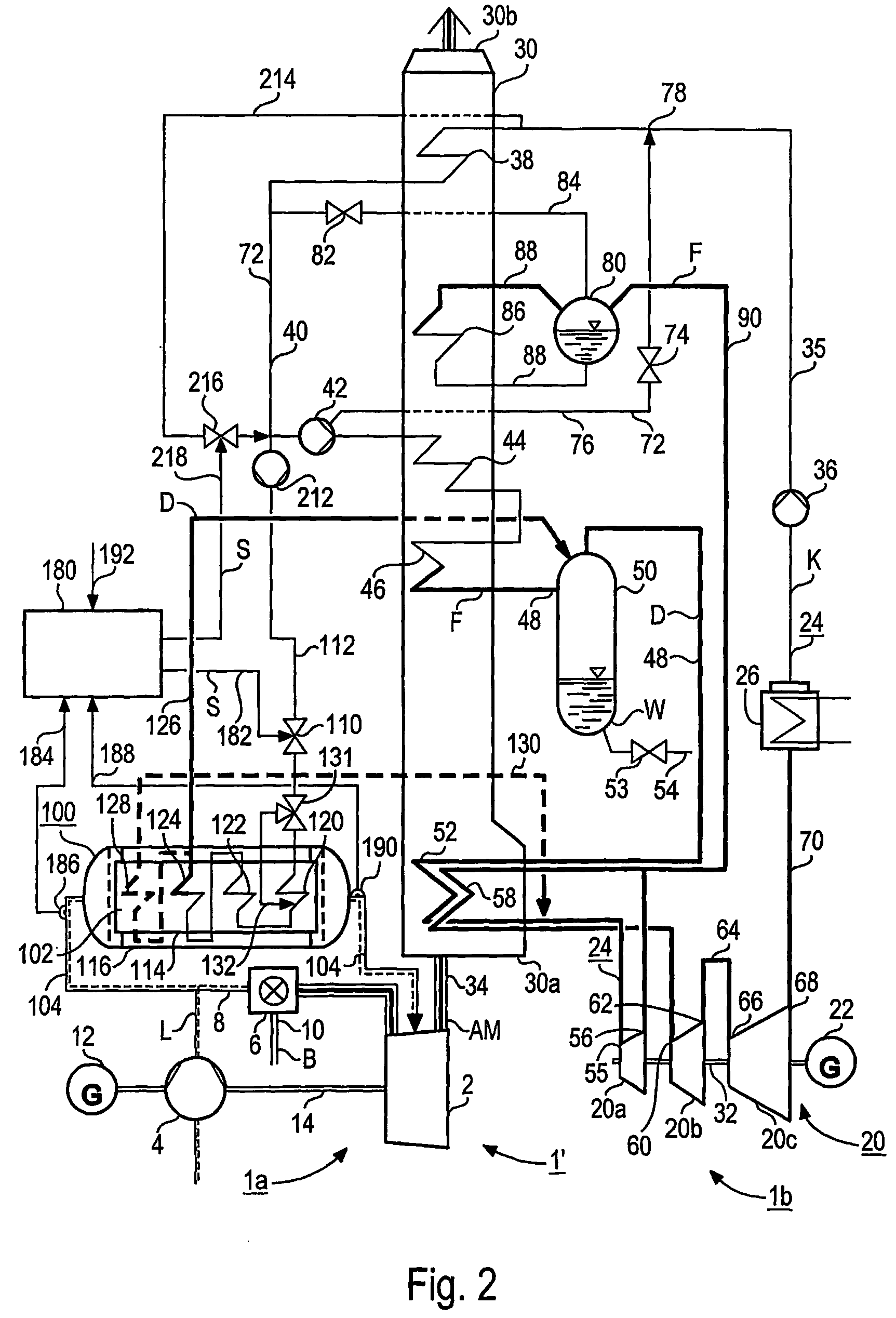
[0032]The gas and steam turbine 1, 1′, 1″ according to FIG. 1, FIG. 2 and FIG. 3 each comprises a gas turbine unit 1a and a steam turbine unit 1b. The gas turbine unit 1a comprises respectively a gas turbine 2 with connected air compressor 4 and a combustion chamber 6 preceding the gas turbine 2 which is connected to a fresh air pipe 8 belonging to the air compressor 4. A fuel line 10 flows into the combustion chamber 6 of the gas turbine 2. The gas turbine 2 and the air compressor 4 as well as a generator 12 are on a common shaft 14.

[0033]The steam turbine unit 1b comprises a steam turbine 20 with connected generator 22 and in a water-steam circuit 24, a condenser 26 downstream of the steam turbine 20 as well as a steam generator 30 intended as a waste heat steam generator for the gas and steam turbine 1. The steam turbine 20 consists of a first pressure stage or a high-pressure component 20a and a second pressure stage or a medium-pressure component 20b as well as a third pressure...


PUM


Abstract

The aim of the invention is a device for coolant cooling in a gas turbine which, with a relatively simple construction and low plant complexity permits a particularly high degree of efficiency in using the heat produced on cooling the coolant from a gas turbine. Said aim is achieved, whereby a number of interconnected evaporator tubes for a flow medium, are arranged in a coolant channel, connected to a gas turbine, to form forced throughflow steam generator. Said device is preferably used in a gas and steam unit with a waste heat steam generator on the exhaust gas side of a gas turbine, the heating surfaces of which are connected into the water-steam circuit of a steam turbine. The evaporator tubes of the device are thus connected on the inlet side by means of supply line to the feed water train of the water-steam circuit of the steam turbine.

Description

CROSS REFERENCE TO RELATED APPLICATIONS[0001]This application is a continuation of International Application No. PCT / EP02 / 05571, filed May 21, 2002 and claims the benefit thereof. The International Application claims the benefits of European application No. 01113305.5 EP, filed May 31, 2001, both applications are incorporated by reference herein in their entirety.FIELD OF INVENTION[0002]The present invention relates to a device for coolant cooling in a gas turbine. Furthermore, it relates to a gas and steam turbine with a waste heat steam generator on the exhaust gas side of a gas turbine, the heating surfaces of which are connected into the water-steam circuit of a steam turbine.BACKGROUND OF INVENTION[0003]A gas turbine, in particular in a gas and steam turbine, is usually used to generate electrical energy. To increase the performance of the gas turbine and thus to achieve the highest possible degree of efficiency, efforts are made to achieve a particularly high temperature of th...

Claims


Application Information

Patent Timeline
Patent Type & Authority Patents(United States)
IPC IPC(8): F02C7/12F01K23/10F02C6/18F02C7/00F02C7/18F22B1/18
CPCF01K23/106F02C7/185F22B1/1838F28F9/26Y02E20/16Y02T50/675Y02E20/14Y02T50/60
Inventor FRANKE, JOACHIMSCHMID, ERICH
Owner SIEMENS AG
Why Eureka
Try Eureka