

Microfluidic devices incorporating improved channel geometries
a microfluidic device and geometries technology, applied in the direction of electrolysis, diaphragms, isotope separation, etc., can solve problems affecting the operation of the system
- Summary
- Abstract
- Description
- Claims
- Application Information
AI Technical Summary
Problems solved by technology
Method used
Image

Examples
example 1
Multisample Analysis
[0097]A 16 sample capacity device, or LabChip™, having the geometry shown in FIG. 3, was fabricated from a 100 mm diameter white crown glass wafer having a thickness of 500 μm. A wafer was used for its compatibility with most commercially available photolithography equipment. Channels 75 μm wide and 12 μm deep, and having the configuration shown, were etched in the glass substrate using standard photolithographic techniques. Holes were drilled through a separate piece of glass 5 inches on a side, whereby the holes corresponded to the termini of the various channels. The two pieces of glass were thermally bonded to form the channel and well structure shown. The device having dimensions of 22.4 mm×37 mm was cut from the larger material.
[0098]Sieving buffer was prepared by weighing 2.5 grams GeneScan Polymer (Perkin Elmer Corp.), 0.5 g of Genetic Analysis Buffer (Perkin Elmer Corp.) and 2.5 ml water into a 20 ml scintillation vial, which was then vortexed for 30 sec...
example 2
Determination of Cross Contamination Levels for Successive Samples
[0111]In order to ascertain whether successive runs in the device experienced any cross contamination of samples, two different nucleic acid fragment samples and a plain buffer sample were run in succession and examined for contaminating effects.
[0112]Each well of the 16 well device described above, was loaded with either the PCR Marker, the PhiX174 cleaved with HAEIII or plain buffer. The wells were loaded such that they would be injected successively in this order. The fluorescence data for each run was plotted as a function of time.
[0113]FIGS. 7A, 7B and 7C show plots of successive injections of PCR Marker, PhiX174 / HaeIII and buffer blanks. FIG. 7B illustrates that no spurious fluorescence peaks are detectable bleeding over from the previous PCR Marker run, into the PhiX174 / HaeIII run. Further, FIG. 7C shows that even in a plain buffer run, there are no detectable levels of cross contamination from the prior DNA co...
example 3
Narrow Channel Injection
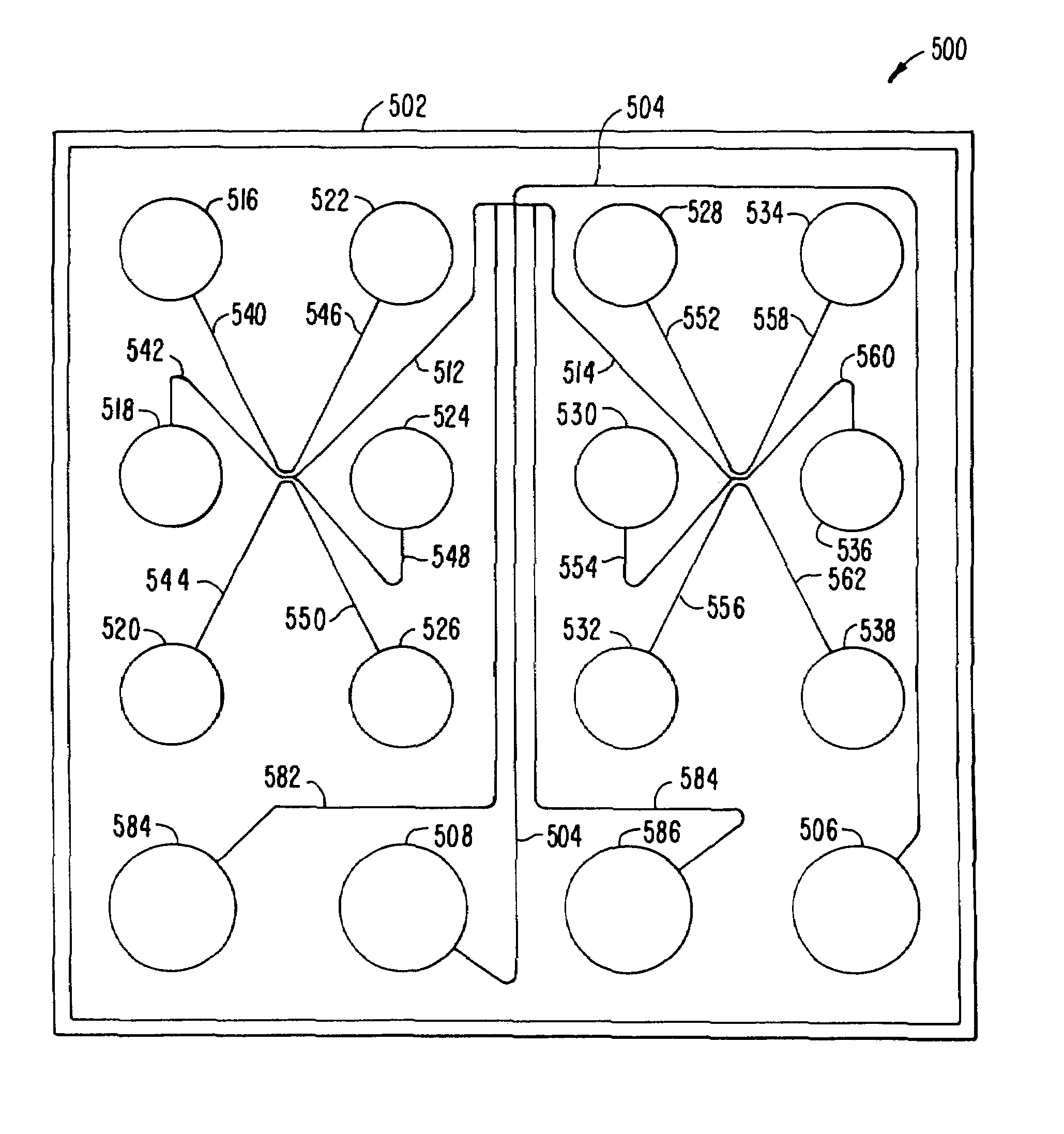
[0114]A microfluidic device incorporating the channel geometry shown in FIG. 5, was prepared as described in Example 1, above, except that the width of all channels of the device was reduced to 30 μm, while the channel depth was maintained at approximately 12 μm. This was used to compare with a microfluidic device having the geometry shown in FIG. 4, but having channel widths of approximately 70 μm, as described in Example 1. The length of the separation channels in the two devices was substantially equivalent.
[0115]The two devices were prepared with sieving buffer, as described above, and each was used to separate a nucleic acid standard 100 base pair ladder, commercially available from Promega Corp., Madison Wis. The results of the separations in the narrow channel and wide channel device are illustrated in FIGS. 8A and 8B, respectively. As is readily apparent, the resolution obtained in the narrow channel device (FIG. 8A) is substantially enhanced over the...
PUM
| Property | Measurement | Unit |
|---|---|---|
| width | aaaaa | aaaaa |
| width | aaaaa | aaaaa |
| depth | aaaaa | aaaaa |
Abstract
Description
Claims
Application Information