Method of removing and replacing catalyst in a multi-reactor cascade configuration

a multi-reactor cascade and catalyst technology, applied in the field of multi-reactor cascade replacement methods, can solve the problems of catalyst inactivation, catalyst regeneration can take a considerable amount of time, and the entire reactor operation must be stopped during catalyst replenishment, so as to reduce the frequency of costly catalyst replacement, reduce the cost of catalyst, and increase the removal of older catalysts

Inactive Publication Date: 2006-04-25
CONOCO INC
View PDF15 Cites 11 Cited by
  • Summary
  • Abstract
  • Description
  • Claims
  • Application Information

AI Technical Summary

Benefits of technology

[0017]The present invention diminishes the frequency of costly catalyst replacement in a multi-reactor cascade configuration (i.e., series rather than parallel arrangement) to maintain a given catalyst age profile. Catalyst cost is reduced by decreasing removal of the newest catalyst and increasing removal of older catalyst. By increasing the efficiency of use of catalyst in a serial multi-reactor catalytic process, under conditions conducive to obtaining the desired level of catalytic activity, catalyst renewal can be reduced compared to conventional catalyst replacement regimes.

Problems solved by technology

In some cases, this catalyst inactivation is due to gradual poisoning by a contaminant (e.g., sulfur, or metals) in a reactant feedstock, or by deposition of the product of an undesired side reaction (e.g., “coking”).
One drawback of these approaches is that the entire reactor operation must be halted during catalyst replenishment.
Regeneration of the catalyst can take a considerable amount of time, causing appreciable reactor downtime and loss of productivity.
Moreover, the catalyst that is removed is often only partially spent, and is replaced by fresh catalyst or routed to a regeneration system, which increases the cost of the process.
Difficulties with respect to withdrawal of expended catalyst occur due to commingling of fresh or partially expended catalyst with expended catalyst withdrawn from the bottom of the catalyst bed in ebulliated bed systems.
Sufficient fresh make-up catalyst is added to the second stage reactor to replace the used catalyst withdrawn there, and only sufficient fresh catalyst is added to the first stage reactor to replace any catalyst transfer losses.
A drawback of most present day catalyst replacement regimes is that they fail to adequately conserve the amount of new or fresh catalyst that is consumed in the overall operation.
This is especially problematic in slurry bubble or fluidized bed reactors, which typically employ higher reactant flow rates and space velocities, and use smaller, more highly active catalyst beds than their fixed bed or plug-flow counterpart reactors.
While the fouled or spent catalyst can usually be expected to concentrate in the fixed bed region that first contacts the reactant fluids or gases, and can be selectively removed by a counterflow catalyst removal system, this is not possible with slurry bubble fluidized catalyst beds.

Method used


Image

  • Method of removing and replacing catalyst in a multi-reactor cascade configuration
  • Method of removing and replacing catalyst in a multi-reactor cascade configuration
  • Method of removing and replacing catalyst in a multi-reactor cascade configuration

Examples


Embodiment Construction

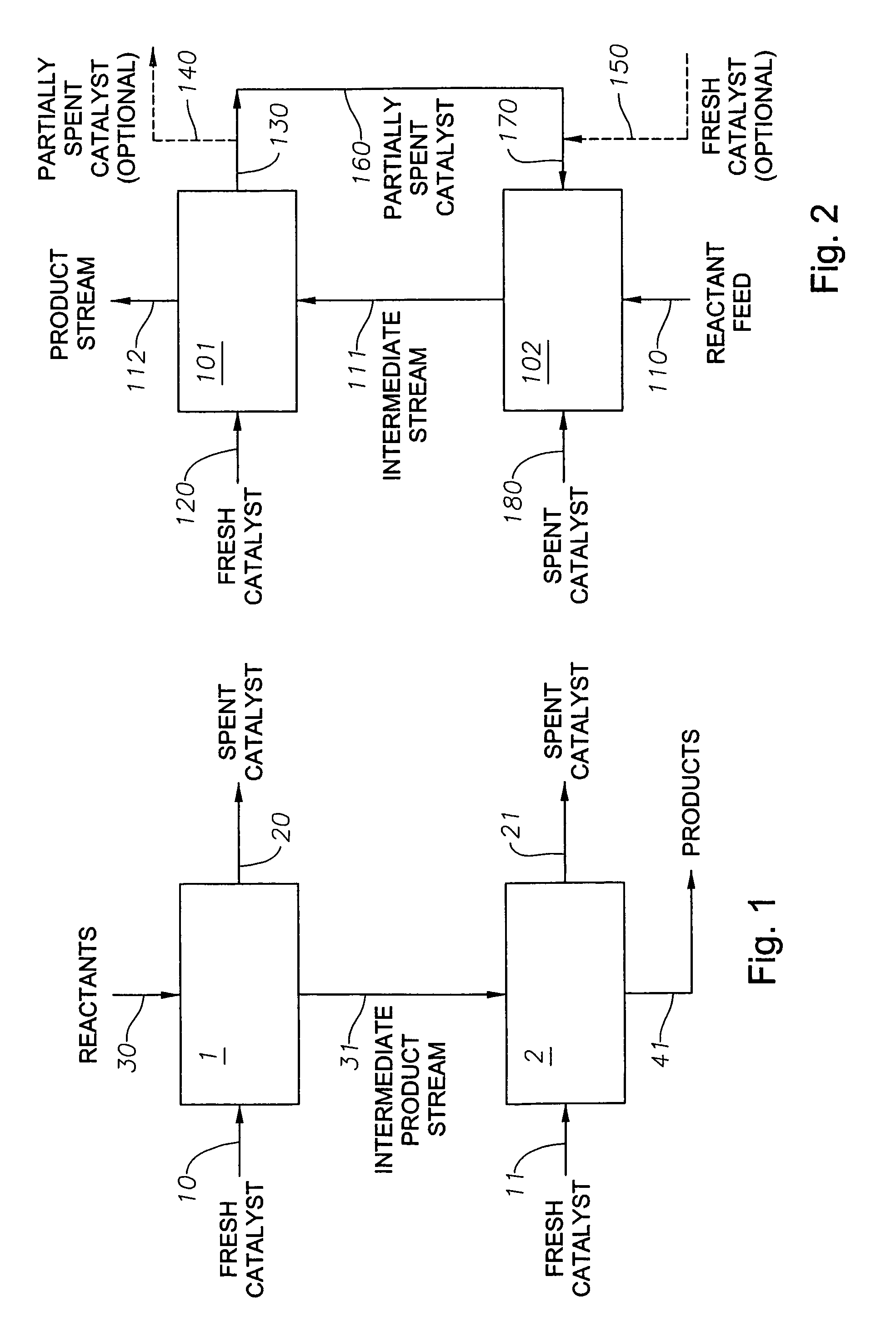
[0024]To optimize both the productivity and the economics of a catalytic process carried out inside a series of catalytic reactors, a defined program of catalyst withdrawal and replacement has been devised. The program offers an improvement over conventional catalyst replacement methods, especially in a series of multiphase slurry bubble or fluidized bed catalytic reactors where the age distribution of the catalyst particles is substantially uniform. By way of illustration only, as in FIG. 1, a multi-reactor series comprising two or more reactors and catalyst recycling, replacement, or replenishment means is employed. The reactors are configured for serial reactant flow from one reactor to the next. The same kind of catalyst is employed in the reaction zone of each reactor. Each reaction vessel and catalyst replacement means can be similar to that described in U.S. Pat. No. 5,733,440, the disclosure of which is incorporated herein by reference. The catalyst may operate as a fixed, e...


PUM

PropertyMeasurementUnit
equilibrium ageaaaaaaaaaa
catalytic activityaaaaaaaaaa
chemical compositionsaaaaaaaaaa

Abstract

A defined catalyst withdrawal and replacement program for optimizing the productivity and the economics of catalyst consumption in a multi-reactor system is disclosed. Catalyst cost is reduced by minimizing removal of the newest catalyst and maximizing removal of older catalyst to achieve an overall reduction of catalyst age in the multi-reactor system.

Description

CROSS-REFERENCE TO RELATED APPLICATIONS[0001]Not applicable.BACKGROUND OF THE INVENTION[0002]1. Field of the Invention[0003]The present invention relates to methods of removing and replacing catalyst in a multi-reactor series. More particularly, the invention relates to such methods in which a predetermined quantity of at least partially spent catalyst is removed from the first of a plurality of reaction vessels and is introduced into a second reaction vessel, and a like amount of fresh catalyst is introduced into the first reaction vessel.[0004]2. Description of Related Art[0005]The use of solid catalysts in industrial catalytic reactors is well known, especially in the field of petroleum refining. Various catalytic distillation processes, fluid catalytic cracking processes, catalytic hydrocracking processes, catalytic reforming processes and catalytic hydrotreating processes, for example, are well documented in the literature. The catalysts employed in those processes have a varie...

Claims


Application Information

Patent Timeline
Patent Type & Authority Patents(United States)
IPC IPC(8): C10G35/00C10G69/02C10G69/14C10G51/02B01J8/00B01J8/18C10G11/02C10G35/06C10G49/02
CPCB01J8/0035B01J8/1809C10G49/02C10G11/02C10G35/06B01J2208/00707B01J2219/0004
Inventor ROCKWELL, JAMES L.
Owner CONOCO INC
Why Eureka
Try Eureka