Method of synthesising carbon nano tubes

a carbon nanotube and carbon nano technology, applied in the field of carbon nanotube synthesis, can solve the problems of additional procedural steps, high impact depth on the surface of the catalyst layer, and clearly is a significant economic disadvantage, and achieve the effects of simple and rapid manner, enhanced physical, chemical and/or conductive properties of said carbon nanotubes, and high procedural flexibility

Inactive Publication Date: 2006-04-25
ELECTROVAC FABATION ELEKTRO TECHNR SPEZIALARTIKEL GES +1
View PDF34 Cites 37 Cited by
  • Summary
  • Abstract
  • Description
  • Claims
  • Application Information

AI Technical Summary

Benefits of technology

[0013]The object of the invention is achieved by a method of synthesising CNT on a catalyst layer formed on a support member, by catalytic deposition of carbon from a gaseous phase, whereby an ion beam is used prior to, during and / or after formation of said carbon nano tubes for modifying the physical, chemical and / or conductive properties of said carbon nano tubes. Synthesising CNTs by performing this method is advantageous due to its high procedural flexibility. The use of ion beam shows a variety of applications which also comprises the formation of the catalyst layer on a support member, as well as a further preparation thereof. Thus, the subsequent in-situ growth of nano tubes on the catalyst is provided in a highly controlled manner. When forming the catalyst, it is preferable, that ion beam is used with regard to catalytically active particles. This is advantageous, since a deposition may be performed directly on the support member without the need of any additional means. In relation to preparatory purposes of a catalyst layer, irrespective of its formation, the application of ion beam is advantageous since the impact of ions on the surface of the catalyst layer does not cause high impact depths thereon and, thus, no detriments to the surface and / or the catalytical particles thereof. Further, preparing a catalyst layer prior to the development of CNTs by the use of ion beam may comprise forming defined (isolated) local areas of catalytical active particles on said layer or even single catalytical active particles, thus providing control of the subsequent growth of CNTs, in particular in relation to their vertical alignment. Such a control may also be obtained when ion beam is used during the growth of CNTs, thus physical, chemical and / or conductive properties of said CNTs may be modified. After formation of carbon nano tubes the application of ion beam is preferable, because already developed CNTs may be easily altered according to need. Thus, physical, chemical and / or conductive properties of said carbon nano tubes can be enhanced in a very simple and rapid manner.

Problems solved by technology

Preparing an existing catalyst layer by the use of electron beams, in particular in relation to photolithographical methods, especially the exposure, results in high impact depths on the surface of the catalyst layer.
This does not often give a favourable result because the impact of electrons might easily damage the catalyst and additional procedural steps are necessary.
This clearly is a significant economic disadvantage when mass production is required.
Etching methods which are preferably used in industrial mass production in the field of nano technology are time consuming processes since a number of procedural steps are needed for the preparation of a catalyst layer.
This can easily cause detriments to the catalytic particles and a proper synthesis of a CNT subsequent to the preparation of a catalyst layer is not satisfying.
It might even result in hindering the entire process of synthesising CNTs.

Method used


Image

  • Method of synthesising carbon nano tubes
  • Method of synthesising carbon nano tubes
  • Method of synthesising carbon nano tubes

Examples


Embodiment Construction

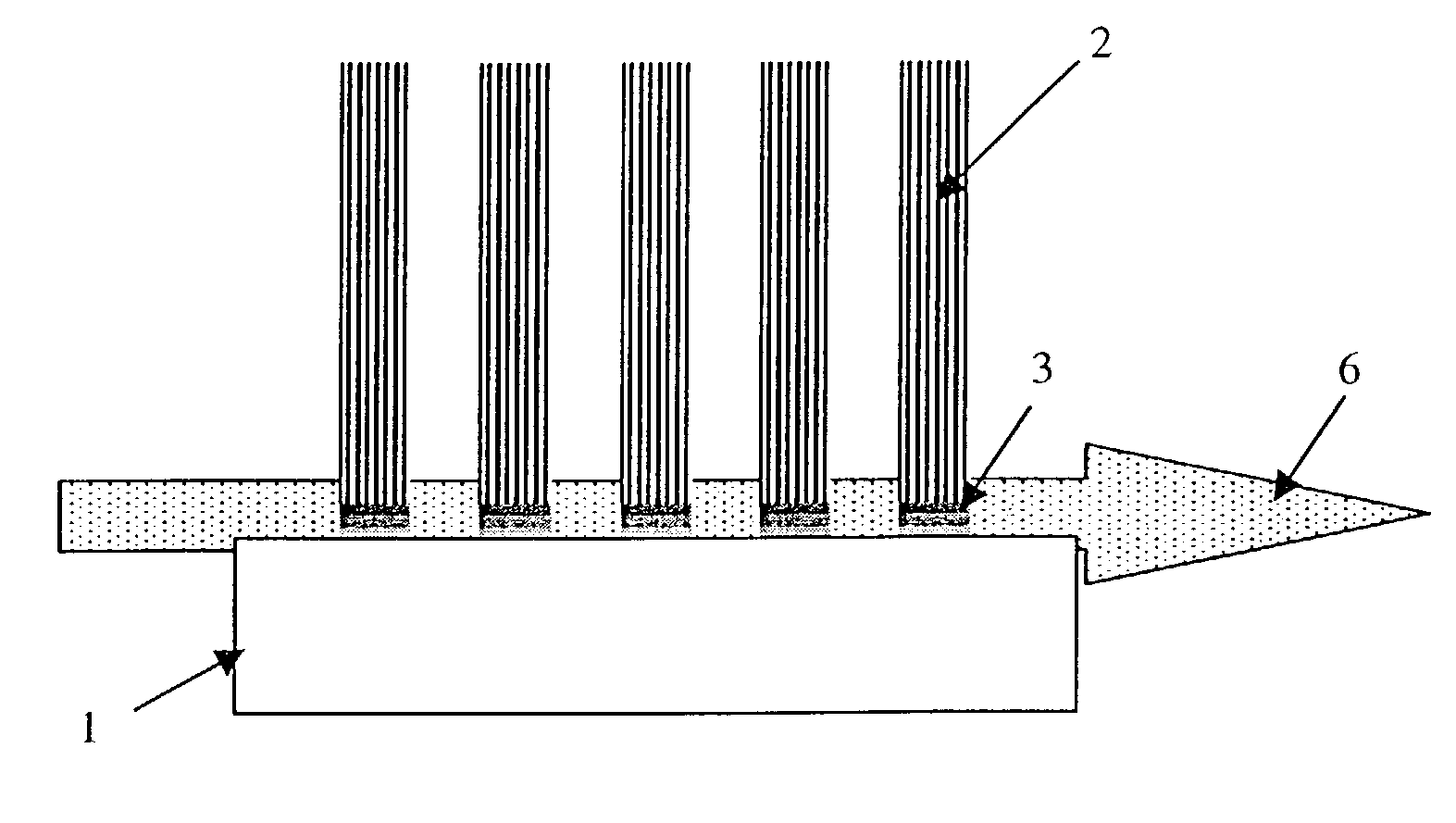
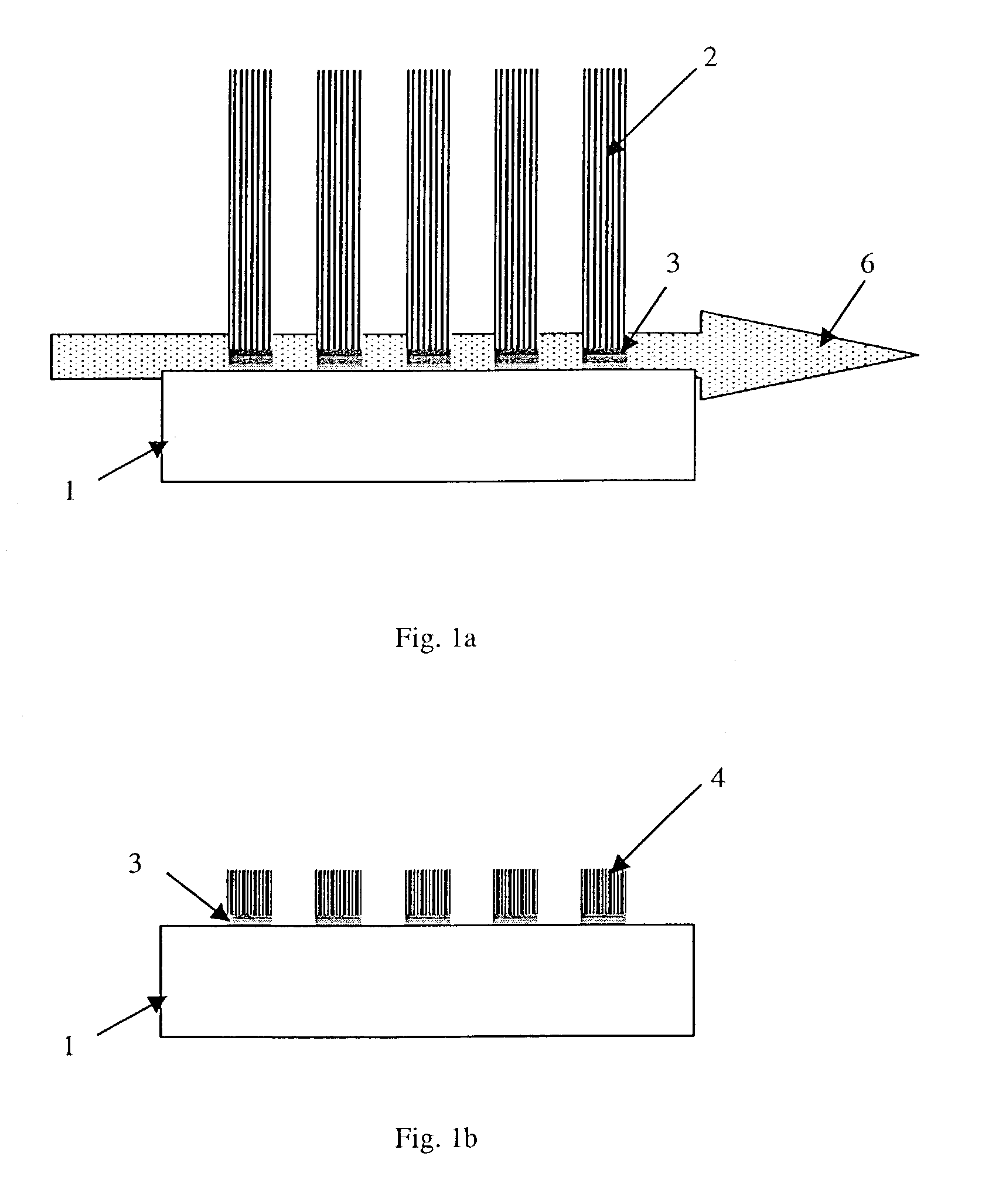
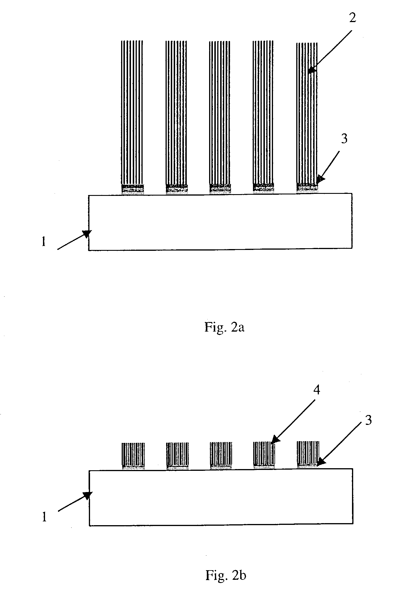
[0055]FIGS. 1a and 1b show a first preferred embodiment according to the invention in which prior to the formation of carbon nano tubes a catalyst layer is formed from a gaseous phase comprising catalysts and deposited on the support member by the use of ion beam. In particular, in FIG. 1a an organometallic gas 6 is injected forming a jet above the support member 1. Controlled ion beams 2 are pointing towards the support member 1. When the controlled beams 2 comprising Ar+-ions are crossing the gas jet 6 comprising preferably Ni, Co or Fe particles, the ion beams 2 induce decomposition of the gas 6 due to the collision with the metal particles. Tear shaped catalytically active metal particles 3 are formed which are immediately deposited on the surface of the support member 1. According to FIG. 1a the surface of a support member 1 is not entirely coated with the catalytically active particles 3. A precise placement of the particles 3 is conducted by the ion beam 2. The exact position...


PUM

PropertyMeasurementUnit
thicknessaaaaaaaaaa
temperatureaaaaaaaaaa
thicknessaaaaaaaaaa

Abstract

Method of synthesizing carbon nano tubes (CNTs) on a catalyst layer formed on a support member, by catalytic deposition of carbon from a gaseous phase, whereby an ion beam is used prior to, during, and / or after formation of the carbon nano tubes for modifying the physical, chemical, and / or conductive properties of the carbon nanotubes.

Description

CROSS-REFERENCE TO RELATED APPLICATIONS[0001]Not ApplicableSTATEMENT REGARDING FEDERALLY SPONSORED RESEARCH OR DEVELOPMENT[0002]Not ApplicableINCORPORATION-BY-REFERENCE OF MATERIAL SUBMITTED ON A COMPACT DISC[0003]Not ApplicableFIELD OF THE INVENTION[0004]The invention relates to a method of synthesising carbon nano tubes (CNTs) on a catalyst layer formed on a support member, by catalytic deposition of carbon from a gaseous phase.BACKGROUND OF THE INVENTION[0005]Carbon nano tubes are known for their conductive or semiconductive properties due to the elongated tubulous structure. They are used especially in the field of industrial technology. The plurality of industrial applications of CNTs shows the need for improving the production process to obtain higher specific quality at increased quantities.[0006]A number of methods synthesising vertically aligned CNTs are known from prior art. The majority of synthesis comprise a formation of a catalyst layer on which CNTs are developed. Pop...

Claims


Application Information

Patent Timeline
Patent Type & Authority Patents(United States)
IPC IPC(8): C23C16/26C23C16/48D01F9/127B01J37/02B01J37/16C01B31/02C23C16/04C23C16/18C23C16/513C30B23/00C30B33/00
CPCB82Y30/00B82Y40/00C01B31/0233C30B23/00C30B33/00C30B29/02C30B29/605Y10S427/102C01B32/162
Inventor TANG, XINHEMAUTHNER, KLAUSHAMMEL, ERNSTLÖSCHNER, HANSPLATZGUMMER, ELMARSTENGL, GERHARD
Owner ELECTROVAC FABATION ELEKTRO TECHNR SPEZIALARTIKEL GES
Why Eureka
Try Eureka