Near-field light-generating element for producing localized near-field light, near-field optical recording device, and near-field optical microscope

a technology of near-field light and light-generating element, which is applied in the direction of material analysis using wave/particle radiation, instruments, nuclear engineering, etc., can solve the problems of inability to achieve a rectangle, limited recording densities of optical disks typified by compact discs (cds), and inability to produce near-field light intensity

Inactive Publication Date: 2006-04-25
SEIKO INSTR INC
View PDF6 Cites 15 Cited by
  • Summary
  • Abstract
  • Description
  • Claims
  • Application Information

AI Technical Summary

Benefits of technology

[0031]This makes it possible to place the portion of the contour of the minute aperture, where near-field light stron

Problems solved by technology

It is known that optical disks typified by compact discs (CDs) have limited recording densities due to diffraction limit of light.
However, a rectangle is not desirable because there is the possibility that the front end becomes like a blade.
The problem with the aforementioned near-field optical probe or head is that the intensity of near-field light (herein referred to as the light efficiency of the probe) generated from the aperture is small compared with the intensity of the incident light.
T

Method used


Image

  • Near-field light-generating element for producing localized near-field light, near-field optical recording device, and near-field optical microscope
  • Near-field light-generating element for producing localized near-field light, near-field optical recording device, and near-field optical microscope
  • Near-field light-generating element for producing localized near-field light, near-field optical recording device, and near-field optical microscope

Examples


embodiment 1

(Embodiment 1)

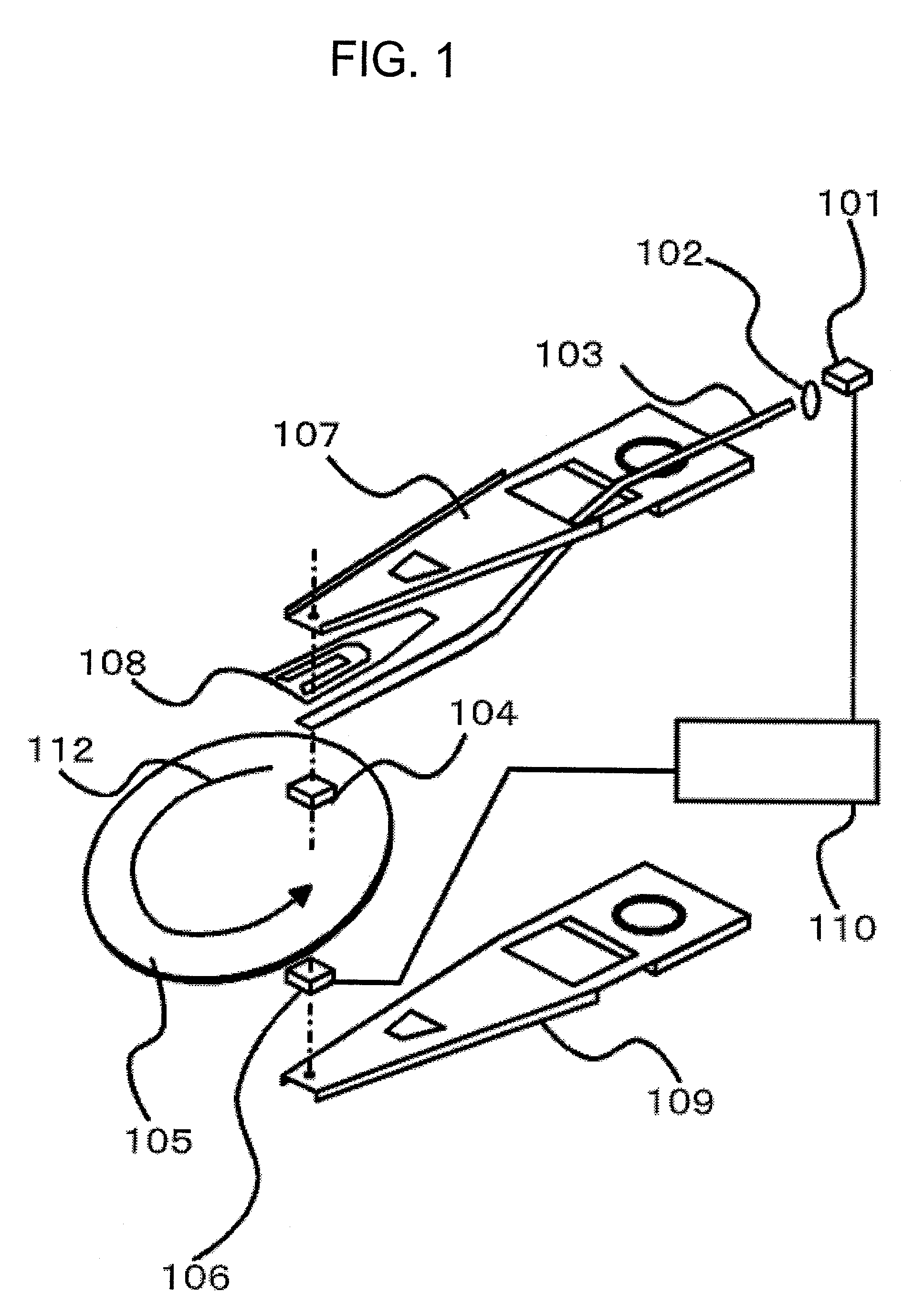
[0057]FIG. 1 is a view illustrating the structure of an information recording-and-reading device of the present embodiment 1. A near-field optical head 104 having a minute aperture (not shown) for producing near-field light is placed at a short distance of tens of nanometers from the surface of a recording medium 105. Under this condition, the recording medium 105 is rotated at a high speed in a direction indicated by the arrow 112. To float the near-field optical head 104 with a constant relative arrangement with the recording medium 105 at all times, a flexure 108 is formed at the front end of a suspension arm 107. The suspension arm 107 can be moved radially of the recording medium 105 by a voice coil motor (not shown).

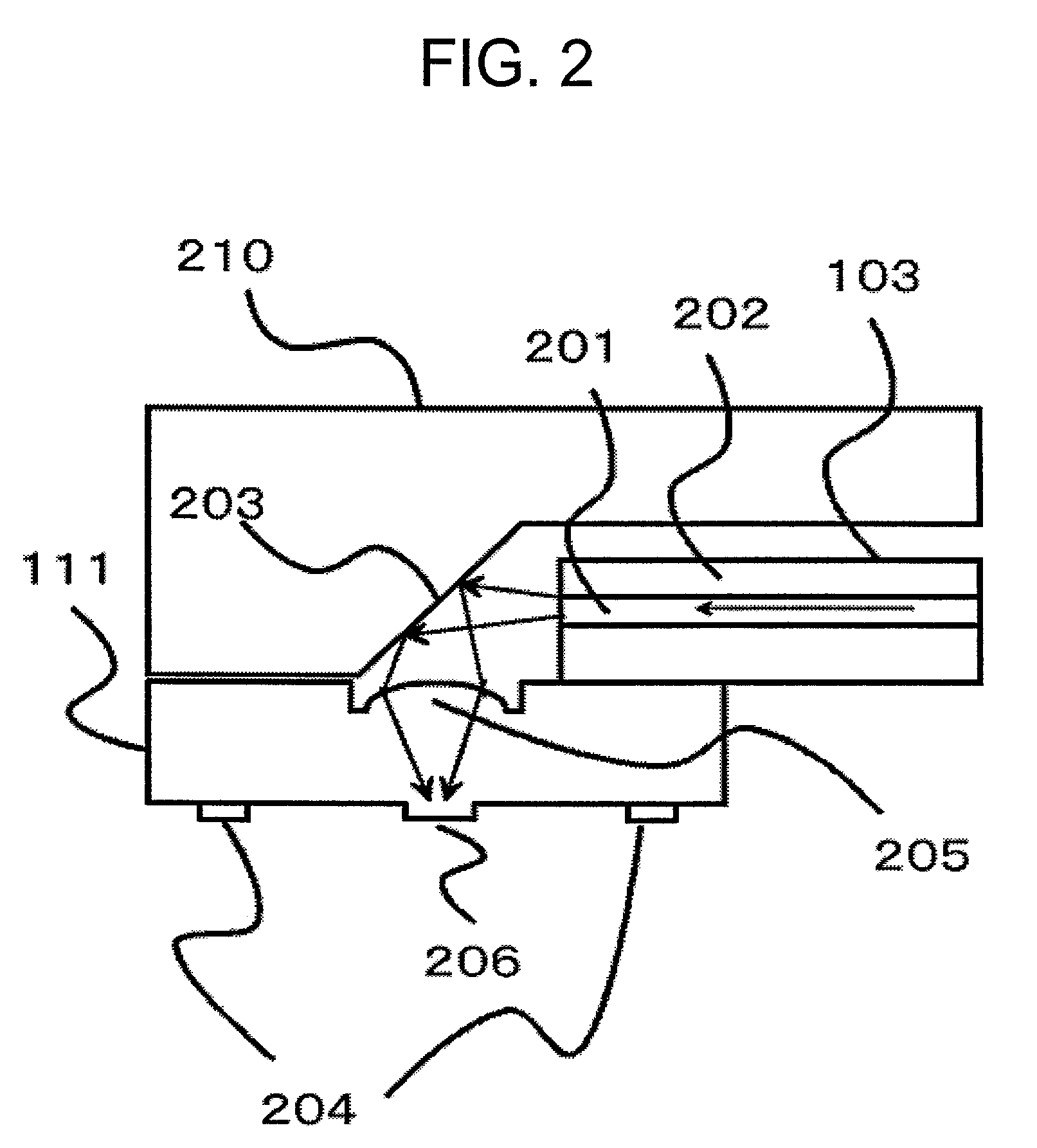
[0058]The near-field optical head 104 is so arranged that the minute aperture is opposite to the recording medium 105. To guide light fluxes from a laser 101 to the near-field optical head 104, an optical waveguide 103 consisting of a core and a clad ...

embodiment 2

(Embodiment 2)

[0072]FIG. 11 is a view showing the configuration of an information recording-and-reading device according to embodiment 2 of the present invention. Its main configurations are similar to those of FIG. 1 described in embodiment 1. Same components are indicated by same symbols. The difference is that in the present embodiment, a method of introducing light into a near-field optical head 104 consists of shaping light from a laser 101 into collimated light 301 using a lens 102, propagating the light through air, and bending the light vertically with a mirror 302. In other respects, the present embodiment is similar to embodiment 1 and thus description of these similar points will be omitted. In the present embodiment, light from the laser 101 is propagated through air and so the light can be admitted into the near-field optical head 104 while preserving the direction of polarization of the light. The important point of the present invention is that near-field light is loc...

embodiment 3

(Embodiment 3)

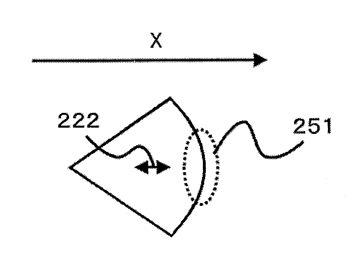
[0073]FIG. 12 is a view showing the vicinities of a minute aperture at the bottom surface of a near-field optical head used in an information recording-and-reading device according to embodiment 3 of the present embodiment. FIG. 12 is similar to FIG. 3 except that an Al light-shielding film 411 deposited on the surface of a triangular pyramid is shown in FIG. 12. One face of the three faces of the triangular pyramid is a Ag film 412 instead of Al. A SiO2 or Al layer is deposited to about 100 nm on the surface of the Al light-shielding film 411 and the Ag film 412, although not shown. The front end of the triangular pyramid is cut horizontally to form an optically minute aperture 206.

[0074]FIG. 13 is a plan view of the minute aperture shown in FIG. 12. The minute aperture 206 has a substantially triangular contour. Its right side is substantially perpendicular to the direction of scan x of the head. The portion in contact with this side is the Ag film 412. The other two...


PUM


Abstract

A near-field light-generating element has a support member and a minute aperture having a size smaller than the wavelength of incident light provided on the support member so as to produce near-field light in response to incident light directed thereto. The minute aperture has a contour in a given plane with one side lying along a line perpendicular to a direction of polarization of the incident light and an opposite side in the given plane defining an apex.

Description

BACKGROUND OF THE INVENTION[0001]1. Field of the Invention[0002]This invention relates to an element for generating near-field light, a head for a high-density information recording device making use of it, and a probe for a high-resolution microscope.[0003]2. Description of the Related Art[0004]Near-field light-generating elements are used in optical heads within optical recording devices for making high-density information recordings and in optical probes within near-field optical microscopes for making observations at high resolutions.[0005]As amounts of information of still images and moving images have increased explosively in recent years, high-density optical recording devices have been developed actively. It is known that optical disks typified by compact discs (CDs) have limited recording densities due to diffraction limit of light. To exceed this limitation, a method utilizing a shorter wavelength of light and a method making use of near-field light have been proposed. An ...

Claims


Application Information

Patent Timeline
IPC IPC(8): H01J3/14G01Q30/04G01Q60/18G01Q60/22G01Q70/10G01Q80/00G11B7/122G11B7/135G11B7/1387G11B11/24
CPCB82Y20/00B82Y35/00G11B7/1387G11B7/1203G01Q60/22B82Y10/00G01Q80/00G11B7/122
Inventor OUMI, MANABUKASAMA, NOBUYUKIMAEDA, HIDETAKAKATO, KENJISHINOHARA, YOKONIWA, TAKASHIMITSUOKA, YASUYUKI
Owner SEIKO INSTR INC
Why Eureka
Try Eureka