Method and apparatus for identifying buried objects using ground penetrating radar

a technology of ground-penetration radar and buried objects, applied in the direction of instruments, measurement devices, antennas, etc., can solve the problems of affecting the service life of the earth, affecting the service life of earth, and affecting the ability of earth-penetration radars to detect objects. the effect of reducing the loss of the earth

Inactive Publication Date: 2006-04-25
UNDERGROUND IMAGING TECH
View PDF40 Cites 101 Cited by
  • Summary
  • Abstract
  • Description
  • Claims
  • Application Information

AI Technical Summary

Problems solved by technology

GPR is similar to upward-looking radar used for air traffic control and meteorology, except that the antenna array is directed toward the ground; thus presenting an entirely different set of technical challenges.
Subsurface industries such as construction, utility location, environmental remediation, and unexploded-ordnance detection have long sought safe, reliable, cost-effective methods for “seeing into the ground.” The utility location market suffers greatly from inadequate location technologies that result in hundreds of millions of dollars in damages, delays, and lost revenue for utility companies and contractors every year, losses that can be reduced significantly by use of GPR.
With One Call, utility line locations are simply painted temporarily on the ground, easily subject to erosion or destruction.
This poor accuracy results in broken utility lines and revenue loss.
These companies often hire a utility locating company or a geophysics company to apply more expensive and time-consuming locating techniques.
Often this includes excavation, the most reliable and expensive conventional method for determining the exact location of utilities.
For instance, extra accuracy may be needed while excavating near an oil pipeline because of the rise of breaking a pipe.
Or, it may be too costly to accidently cut an interstate fiber optic cable carrying important communications.
It is generally more costly than private locating services because it uses computer aided design to produce a permanent record of the location of utilities.
Further, SUE is very expensive.

Method used


Image

  • Method and apparatus for identifying buried objects using ground penetrating radar
  • Method and apparatus for identifying buried objects using ground penetrating radar
  • Method and apparatus for identifying buried objects using ground penetrating radar

Examples


Embodiment Construction

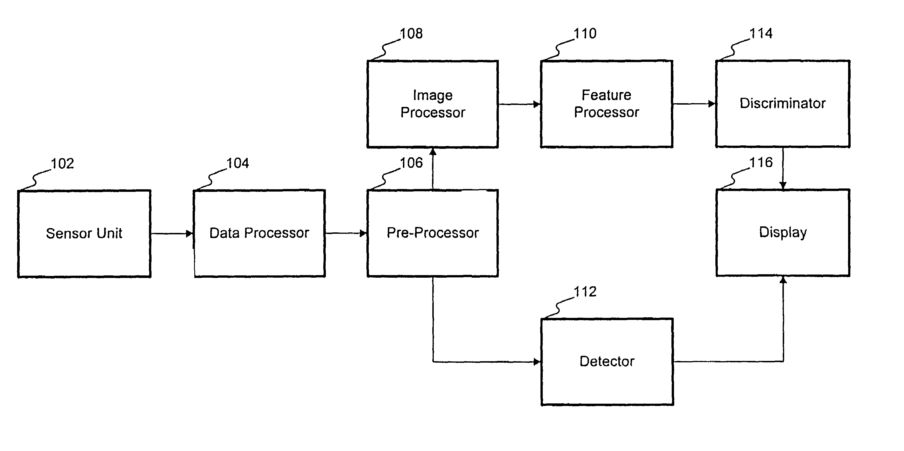
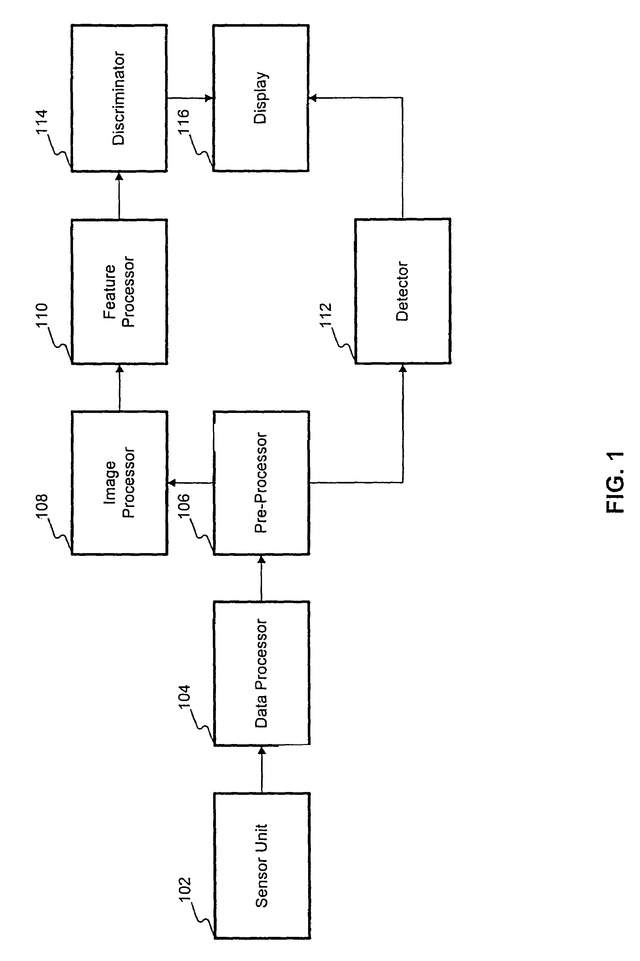
[0029]A method and system is disclosed for identifying buried objects using ground-penetrating radar. FIG. 1 is an embodiment of an apparatus for identifying buried objects using ground-penetrating radar consistent with the present invention. The apparatus of FIG. 1 includes sensor unit 102, data processor 104, pre-processor 106, image processor 108, feature processor 110, detector 112, discriminator 114, and display 116.

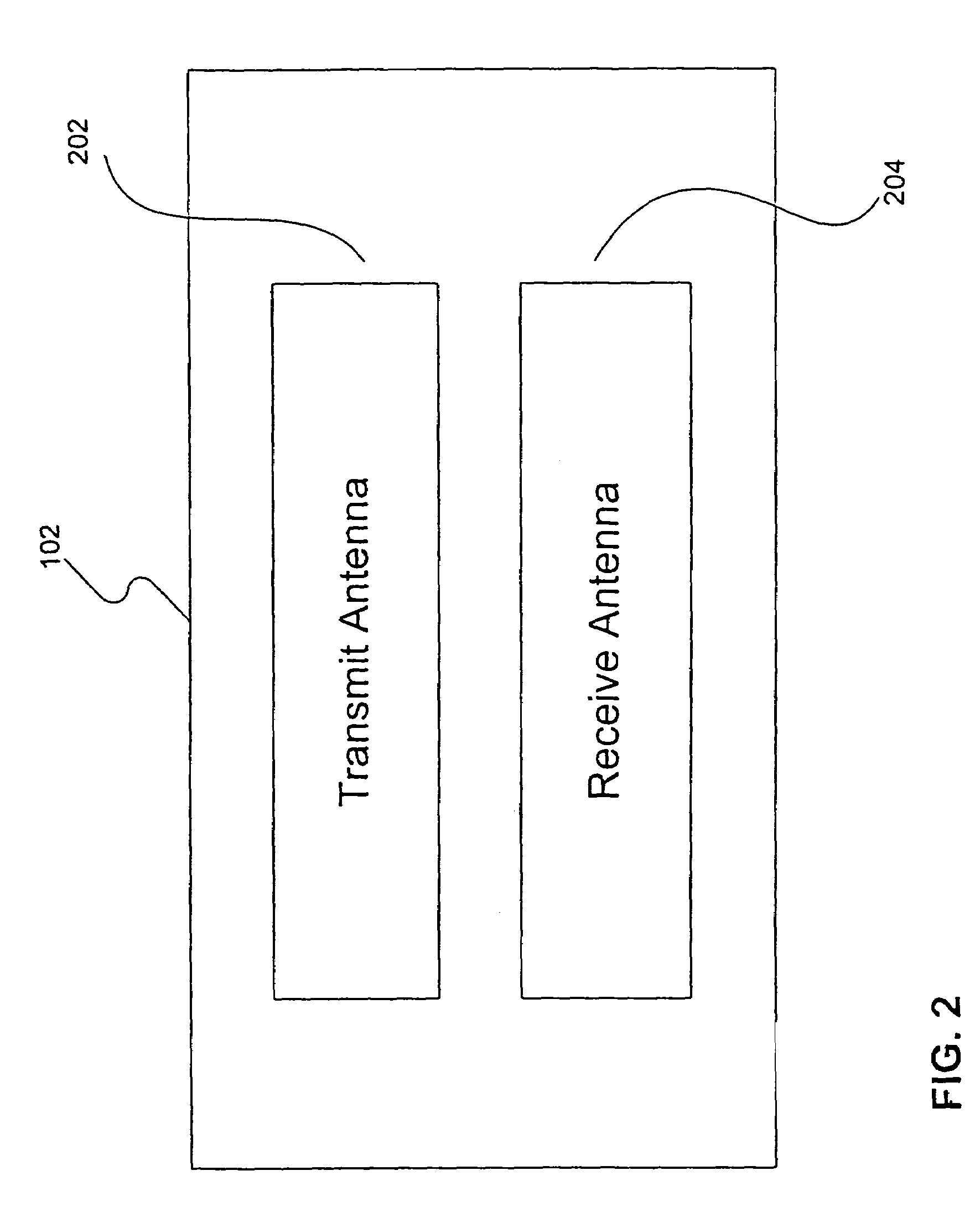
[0030]FIG. 2 is a detailed view of sensor unit 102. An embodiment of sensor unit 102 consistent with the present invention includes transmit antenna 202 and receive antenna 204. Transmit antenna 202 emits GPR waves used to probe for buried objects. Receive antenna 204 receives the transmitted GPR waves as they are reflected from the ground and from objects located beneath the ground. Sensor unit 102 controls the characteristics of the transmitted GPR signal (in some instances receiving support from data processor 104 as will be descried in greater detail below) and ...


PUM


Abstract

An apparatus for identifying a buried object using ground penetrating radar (GPR) in a system containing at least one GPR sensor, comprises a data processor for detecting spatial correlations in data received from a GPR sensor in the apparatus and an image processor capable of building a data structure corresponding to an image of the buried object from data processed by the data processor. A method for identifying a buried object using GPR in a system containing a GPR sensor comprising detecting spatial correlations in data received from the GPR sensor in the system and building a data structure corresponding to an image of the buried object from the received data.

Description

RELATED APPLICATIONS[0001]This patent application is a continuation of U.S. patent application Ser. No. 10 / 118,991 filed Apr. 10, 2002 now U.S. Pat. No. 6,700,526, which is a continuation-in-part of U.S. patent application Ser. No. 10 / 079,807 filed Feb. 22, 2002, which is a continuation of U.S. patent application Ser. No. 09 / 866,575 filed May 29, 2001 (now abandoned), which is a continuation of U.S. patent application Ser. No. 09 / 658,188 filed Sep. 8, 2000 (now abandoned), which is herein incorporated by reference in its entirety and which claims priority to U.S. Provisional Patent Application No. 60 / 284,921 filed Apr. 20, 2001, entitled Method and Apparatus for Identifying Buried Objects Using Ground Penetrating Radar, which is herein incorporated by reference in its entirety.BACKGROUND OF THE INVENTION[0002]The present invention relates to ground-penetrating radar (GPR) systems and methods, and more particularly to ground-penetrating radar systems and methods for identifying burie...

Claims


Application Information

Patent Timeline
Patent Type & Authority Patents(United States)
IPC IPC(8): G01S13/88G01S13/00G01S13/89G01S7/03G01S7/28G01S13/02G01V3/12G01V3/17H01Q3/24H01Q3/26H01Q21/08
CPCG01S7/28G01S13/0209G01S13/88H01Q21/08G01V3/17H01Q3/24H01Q3/2682G01V3/12G01S13/885
Inventor WITTEN, ALAN
Owner UNDERGROUND IMAGING TECH
Why Eureka
Try Eureka