Image pickup apparatus with reduced flicker and automatic level adjusting method of the same

a pickup apparatus and flicker reduction technology, applied in the direction of instruments, television systems, color signal processing circuits, etc., can solve the problem of not being able to suppress in another region, and achieve the effect of suppressing flicker and high quality pictures

Active Publication Date: 2006-04-25
MITSUBISHI ELECTRIC CORP
View PDF24 Cites 49 Cited by
  • Summary
  • Abstract
  • Description
  • Claims
  • Application Information

AI Technical Summary

Benefits of technology

[0013]The present invention is implemented to solve the foregoing problem. It is therefore an object of the present invention to provide an image pickup apparatus and its automatic level adjusting method capable of obtaining high quality pictures with suppressing the flicker even if the frequency of a power supply varies with regions.

Problems solved by technology

With the foregoing configuration, the conventional automatic level adjusting method has a following problem depending on the frequency of a power supply: Although the illuminance fluctuation period of a fluorescent lamp is 1 / 100 second in a region where the frequency of the power supply is 50 Hz, that in the region where the frequency of the power supply is 60 Hz, it is 1 / 120 second.
Thus, the illuminance fluctuation period of the fluorescent lamp varies depending on the frequency of an alternating power supply, and this presents the main cause of the flicker.
As a result, although the flicker is suppressed in one region, it cannot be suppressed in another region because of the different illuminance fluctuation period.

Method used


Image

  • Image pickup apparatus with reduced flicker and automatic level adjusting method of the same
  • Image pickup apparatus with reduced flicker and automatic level adjusting method of the same
  • Image pickup apparatus with reduced flicker and automatic level adjusting method of the same

Examples


embodiment 1

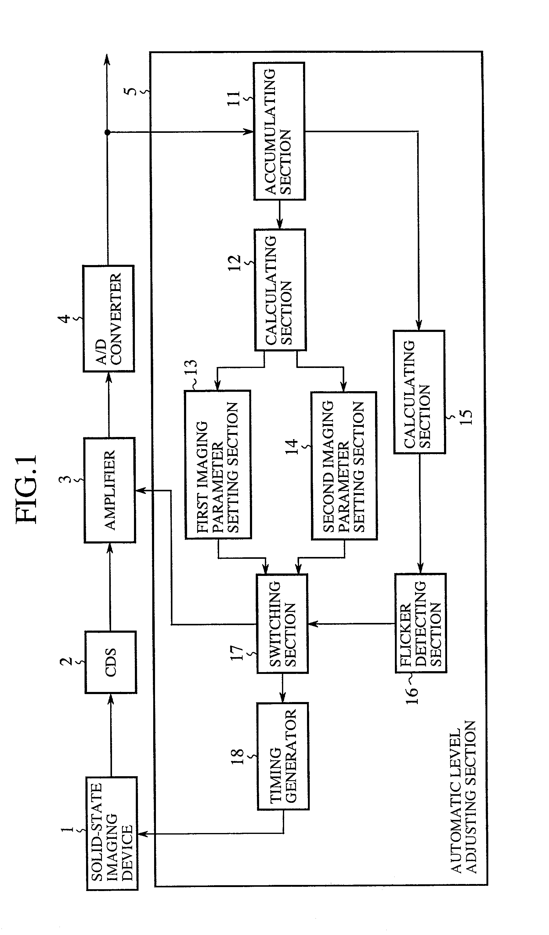
[0043]FIG. 1 is a block diagram showing a configuration of an embodiment 1 of the image pickup apparatus in accordance with the present invention. In FIG. 1, the reference numeral 1 designates a solid-state imaging device such as a CMOS sensor for generating an image signal by the photoelectric conversion of individual pixels at different timings; 2 designates a correlated double sampling circuit (CDS) for canceling noise in the image signal; 3 designates an amplifier for amplifying the image signal; 4 designates an A / D converter for converting the image signal into digital data; and 5 designates an automatic level adjusting section for automatically controlling the charge storage time of the solid-state imaging device 1 and the gain of the amplifier 3.

[0044]In the automatic level adjusting section 5, the reference numeral 11 designates an accumulating section for accumulating a plurality of pixel values on a specified line in a frame; 12 designates a calculating section for carryin...

embodiment 2

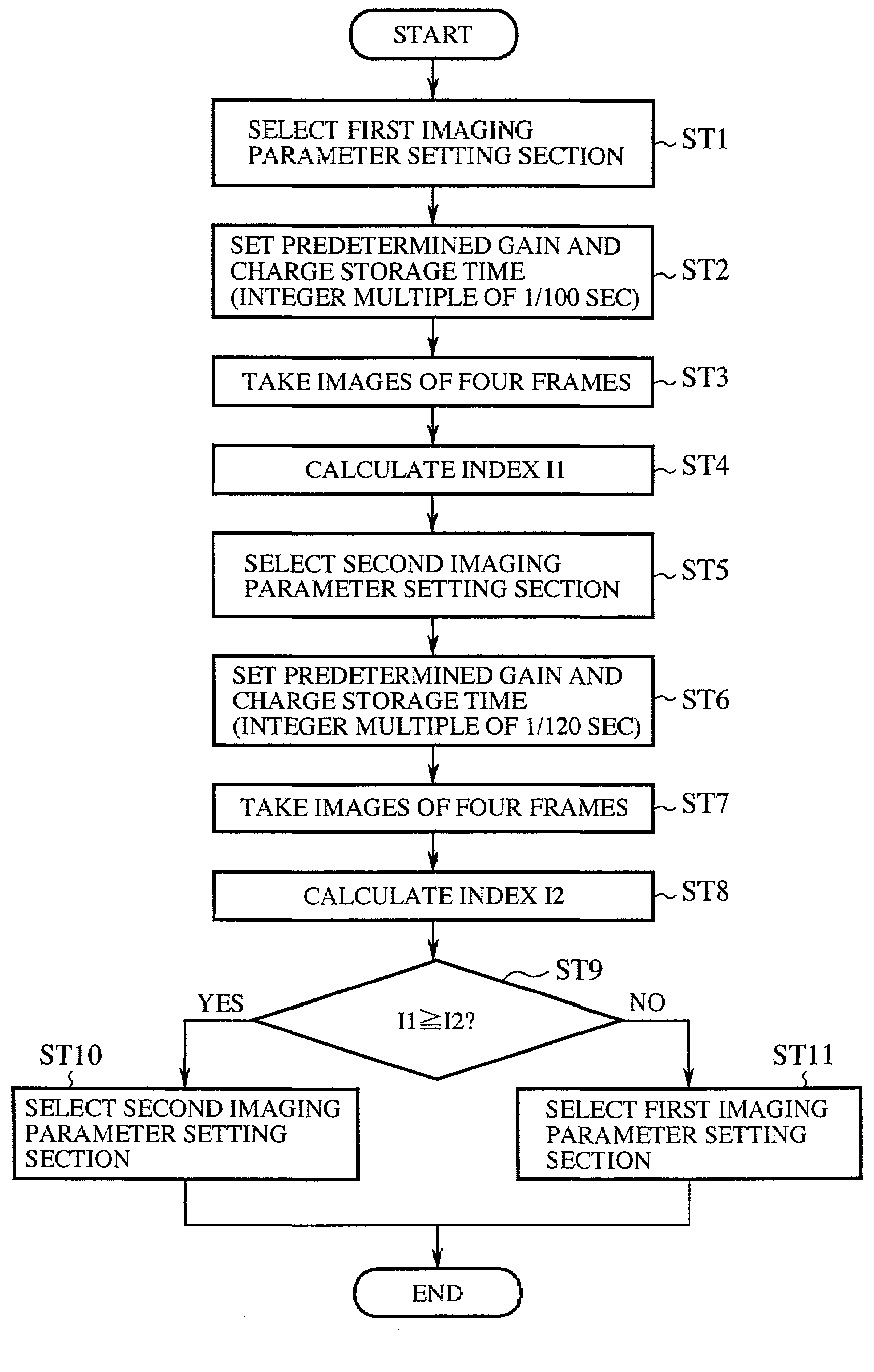
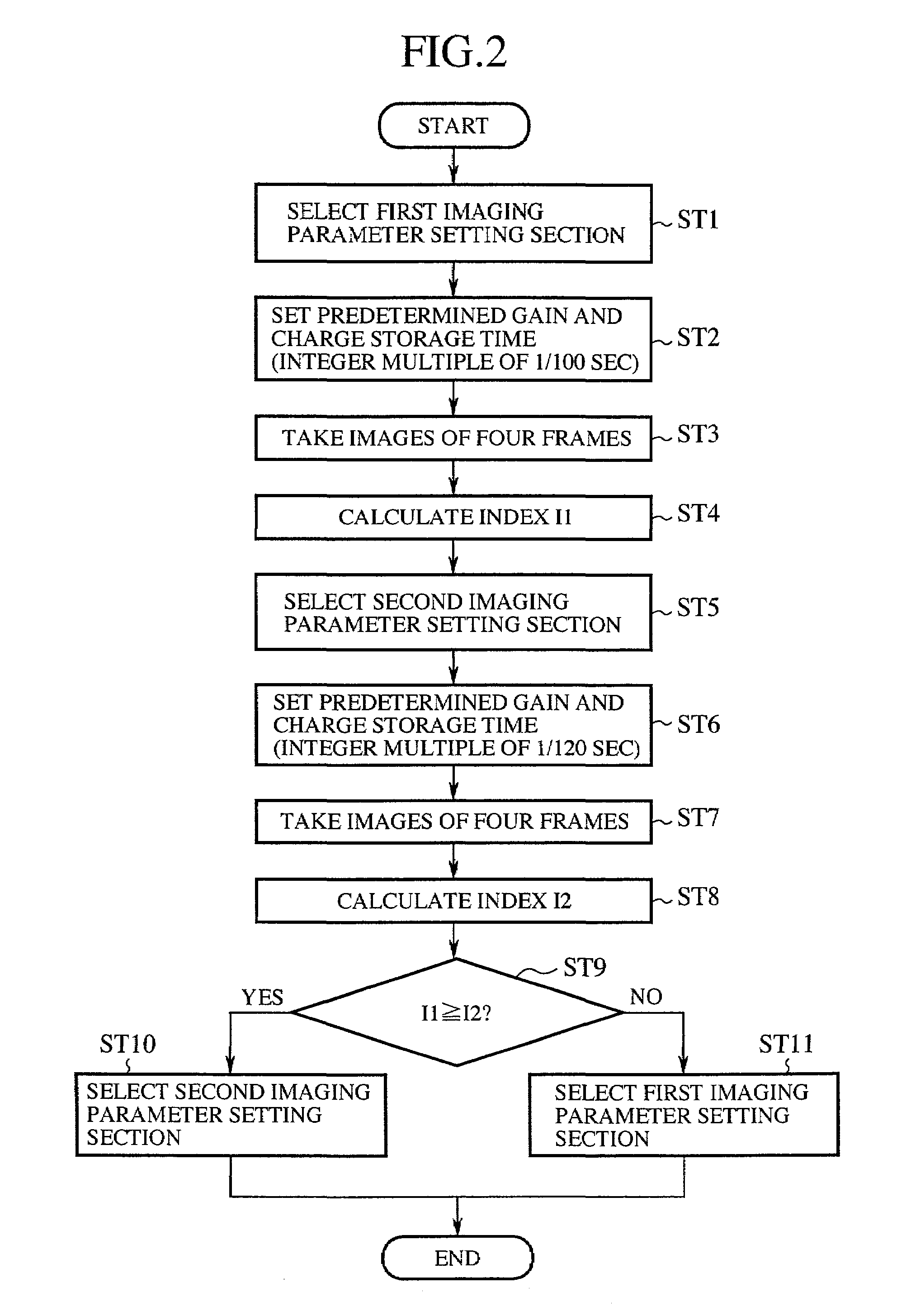
[0074]The present embodiment 2 of the image pickup apparatus in accordance with the present invention is configured such that it can detect the flicker even when the frame period is an integer multiple of 1 / 100 second or an integer multiple of 1 / 120 second.

[0075]Although the foregoing embodiment 1 carries out, when detecting the flicker, the image acquisition by setting the frame period at a value other than an integer multiple of 1 / 100 second or 1 / 120 second in order to positively detect the flicker in either region using the alternating power supply of 50 Hz or 60 Hz, the present embodiment 2 can detect the flicker even if the frame period is an integer multiple of 1 / 100 second or 1 / 120 second, making it possible to handle such a case where the frame rate must be 15 fps because of the limitations of the apparatus.

[0076]Since the main configuration of the present embodiment 2 of the image pickup apparatus is the same as that of the foregoing embodiment 1, the description thereof is...

embodiment 3

[0086]The present embodiment 3 of the image pickup apparatus in accordance with the present invention makes a decision, when the movement of the subject or the change in the imaging environment takes place, as to whether the fluctuations in the projection output values are based on the flicker or on the movement of the subject or the change in the imaging environment, thereby suppressing the flicker appropriately when it occurs.

[0087]FIG. 6 is a block diagram showing a configuration of the calculating section 15 of the embodiment 3 of the image pickup apparatus in accordance with the present invention. In FIG. 6, the reference numeral 21 designates a flicker index calculating section; reference numerals 22, 23, 24 and 25 each designate a memory for storing a flicker index in sequence; the reference numeral 26 designates a sum calculating section for calculating the sum of the flicker indices supplied from the flicker index calculating section 21 and memories 22–25; and 27 designates...


PUM


Abstract

An image pickup apparatus includes a solid-state imaging device, an accumulating section, first and second imaging parameter setting sections, a calculating section, a flicker detecting section, and a switching section. The accumulating section calculates a projection output value of a predetermined line in a frame. The calculating section calculates inter-frame variations of the projection output values, and calculates a flicker index from the variations of a predetermined number of frames. The flicker detecting section detects the flicker from the index, and controls the switching section in response to the detection result of the flicker, so that the switching section selects either the setting signals from the first imaging parameter setting section or the setting signals from the second imaging parameter setting section. Thus, the charge storage time of the solid-state imaging device is set at either an integer multiple of 1/100 second or an integer multiple of 1/120 second in response to the frequency (50 Hz or 60 Hz) of a power supply of the fluorescent lighting. The image pickup apparatus can solve a problem of a conventional apparatus in that it is difficult for the conventional apparatus to suppress the flicker in regions where the frequency of the power supply differ from each other.

Description

BACKGROUND OF THE INVENTION[0001]1. Field of the Invention[0002]The present invention relates to an image pickup apparatus and automatic level adjusting method applicable to a digital still camera and the like, and more particularly to an image pickup apparatus and automatic level adjusting method capable of suppressing flicker generated in fluorescent lighting.[0003]2. Description of Related Art[0004]When using a CMOS sensor as a solid-state imaging device of an image pickup apparatus such as a digital still camera for taking still pictures, bright and dark horizontal striped patterns can occur in pictures taken in an environment in which brightness varies periodically such as in the fluorescent lighting. They arise from the difference between the timing of the flickering of the fluorescent lighting and that of the photoelectric conversion of individual pixels of the pictures. This phenomenon is referred to as flicker.[0005]To suppress the flicker, there are such conventional metho...

Claims


Application Information

Patent Timeline
Patent Type & Authority Patents(United States)
IPC IPC(8): H04N9/73H01L27/00H04N11/20H04N5/222H04N5/232H04N5/235H04N5/243H04N5/335H04N5/351H04N5/353H04N5/357H04N5/369H04N5/372H04N101/00
CPCH04N5/235H04N5/243H04N5/2357H04N5/2353H04N23/70H04N23/745H04N23/76H04N23/73
Inventor NAGAOKA, HIDETADAMATOBA, NARIHIROFUJITA, TAKEOSUGIURA, HIROAKIKUNO, TETSUYA
Owner MITSUBISHI ELECTRIC CORP
Why Eureka
Try Eureka